Sign In
Upload
Manuals
Brands
PairGain Manuals
Computer Hardware
150-1111-75
PairGain 150-1111-75 Manuals
Manuals and User Guides for PairGain 150-1111-75. We have
1
PairGain 150-1111-75 manual available for free PDF download: Manual
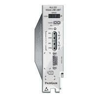
PairGain 150-1111-75 Manual (68 pages)
Line unit
Brand:
PairGain
| Category:
Computer Hardware
| Size: 0.92 MB
Table of Contents
Table of Contents
5
Overview
11
Features
11
Applications
12
Applications Without Higain Doublers
12
Table 1. HDSL Loss over Cables
12
Applications with Higain Doublers
13
Product Description
13
Front Panel
14
Figure 1. HLU-231 List 7E Front Panel
14
Status LED
15
Front Panel Display
15
Table 2. Front Panel Components and Labels
15
Table 3. Status LED Descriptions
15
Table 4. Front Panel Display Messages
16
HLU-231 List 7E Card Connector
17
Figure 2. HLU-231 List 7E Card-Edge Connector
17
Network Management Control Bus
18
Fuse Alarm
18
System Alarm Relay Output
18
Installation
19
Provisioning the HLU-231
19
Figure 3. Installing the HLU-231 into a Shelf
19
Setting Options through SEL and MODE
20
Factory Default Values
20
Displaying System Inventory
21
Connecting to a Maintenance Terminal
21
Maintenance
22
Navigating the Maintenance Terminal Screens
22
System Spans
22
Figure 4. DB-9 RS-232 I/O Pinouts
22
Navigation Keys
23
Selecting an Option
23
Initializing the Maintenance Terminal Screens
23
Figure 5. System Spans
23
Table 5. Navigational Keys on the Maintenance Terminal
23
Maintenance Terminal Main Menu
24
Figure 6. Maintenance Terminal Main Menu
24
Table 6. Maintenance Terminal Screens
24
View Span Status
25
Span Status Screen: Non-Doubler Applications
25
Span Status Screen: Doubler Applications
25
Figure 7. Span Status Screen (no Doubler)
25
Figure 8. Span 1 Status Screen
26
Figure 9. Span 2 Status Screen
26
Span Status Fields, Alarms, and Loopbacks
27
Table 7. Span Status Fields and Descriptions
27
Table 8. HLU-231 Status Menu Messages
28
Set Clock
29
Set Time
29
Figure 10. Set Clock Screen
29
Set Date
30
Update the HRU Time and Date
30
System Settings
30
Figure 11. System Settings Screen
30
DS0 Blocking Option
31
DS1 Line Code Option
31
Margin Alarm Threshold
32
HAIS Selections
32
HDSL Line Voltage Operation
32
Ground Fault Detect
33
System Settings Screen Options
33
Table 9. HLU-231 List 7E System Settings Screen Options
33
Loopback Menu
35
Loopback Menu: no Doubler
36
Loopback Menu: Two Doublers
36
Figure 12. Loopback Menu: no Doubler
36
Figure 13. Loopback Menu with Two Doublers
36
Initiating a Loopback
37
Disable Loopbacks
37
Figure 14. NLOC Loopback Mode in the Maintenance Terminal Main Menu
37
Performance Data Screens
38
Table 10. Errored and Unavailable Seconds Definitions
38
Performance Data Screen: no Doubler
39
Performance Data Screen: with Doubler
39
Figure 15. Performance Data Screen: no Doublers
39
View Performance History
40
Figure 16. Span 3 Performance Data Screen
40
The 7 Day History Screen: no Doubler
41
The 7 Day History Screen: with Doubler
41
Figure 17. 7 Day History Screen for Span 1 (no Doubler)
41
View Alarm History
42
Figure 18. 7 Day History Screen Span 3
42
Alarm History Screen: no Doubler
43
Figure 19. Alarm History Screen for Span 1
43
Table 11. Alarm History Fields and Descriptions
43
Alarm History Screen: with Doubler
44
Circuit ID
44
Figure 20. Alarm History Screen for Span 3
44
System Alarms
45
Retiring System Alarms
45
Table 12. HDSL System Alarms
45
Self Test
46
Loopback Operation
46
Smartjack (SMJK) Loopback
46
Generic Loopback Code (GNLB)
46
Addressable Repeater Loopback Functions
47
Initiating Manual Loopback Sessions
47
Loopback Test Procedures
48
Loopback Operation Without Doublers
49
Loopback Operation with Doublers
49
Figure 21. HLU-231 Non-Doubler Loopback Configurations
49
Figure 22. Doubler Loopback Configurations
50
Table 13. SPLB Loopback Command Set
50
GNLB Loopback Test Procedures
51
A1LB, A2LB, and A5LB Test Procedures
51
A3LB and A4LB Test Procedures
54
Table 14. Addressable 1, 2, 5 (A1LB, A2LB, A5LB) Repeater Loopback Commands
54
Table 15. Addressable 3 and 4 (A3LB and A4LB) Repeater Loopback Commands
55
Appendix A - Technical Specifications
56
Appendixb - Abbreviations
57
Appendix C - Functional Operation
59
Figure 23. HLU-231 Block Diagram
59
Power Consumption
60
Power Consumption: Without Doublers
60
Maximum Power Dissipation
60
Maximum Power Consumption
60
Maximum Current Drain
60
Power Consumption: with Doublers
61
Table 16. HLU-231 List 7E Power Parameters with HDU-451 Doublers, List 1, 2, 3, & 4, and M/M
62
Table 17. HLU-231 List 7E/HDU-451 List 1, 2, & 3 Deployment Guidelines
62
Appendixd - Compatibility
63
T1 Repeater Shelves and Related Equipment
63
Higain Doubler Circuit Deployment
63
Table 18. Higain Doubler Deployment Matrix
64
Appendixe - Product Support
65
Technical Support
65
Warranty
65
FCC Compliance
66
Modifications
66
Standards Compliance
66
Barcode and Configuration Number Information
67
Figure 24. Bar Code Label and Configuration Number
67
Table 19. Bar Code Label and Configuration Number Descriptions
67
Advertisement
Advertisement
Related Products
PairGain 150-1504-14
PairGain 150-1141-24
PairGain 150-1559-01
PairGain 150-1504-15
PairGain 150-1111-65
PairGain 150-1111-08
PairGain 150-1111-06
PairGain 150-1111-64
PairGain 150-1115-12
PairGain 150-1111-81
PairGain Categories
Network Hardware
Remote Control
Touch terminals
Switch
Computer Hardware
More PairGain Manuals
Login
Sign In
OR
Sign in with Facebook
Sign in with Google
Upload manual
Upload from disk
Upload from URL