Sign In
Upload
Manuals
Brands
Oriental motor Manuals
Engine
A Step AZ Series
Oriental motor A Step AZ Series Stepper Manuals
Manuals and User Guides for Oriental motor A Step AZ Series Stepper. We have
2
Oriental motor A Step AZ Series Stepper manuals available for free PDF download: Manual, User Manual
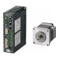
Oriental motor A Step AZ Series Manual (484 pages)
Closed Loop Stepping Motor and Driver Package Function Edition
Brand:
Oriental motor
| Category:
Engine
| Size: 3.7 MB
Table of Contents
Table of Contents
2
Operation
11
Flow of Setting Required for Positioning Operation
16
Setting of Resolution
17
Stored Data (SD) Operation
19
Types of Stored Data (SD) Operation
19
Setting of Data
23
Positioning SD Operation
30
Positioning Push-Motion SD Operation
39
Continuous SD Operation
43
Mode for Link Operation of Operation Data
48
Sequence Function
58
Extended Operation Data Setting
64
Stop Operation
66
Base Current and Stop Current
68
Acceleration/Deceleration Unit
69
Starting Speed
70
Return-To-Home Operation
71
High-Speed Return-To-Home Operation
71
High-Speed Return-To-Home
71
Operation
71
Return-To-Home Operation
73
Macro Operation
87
Types of Macro Operation
87
JOG Operation
88
High-Speed JOG Operation
90
Inching Operation
92
Combined JOG Operation
94
Continuous Operation
96
Speed Control Operation
98
Speed Control Push-Motion Operation
100
Relationship between Operation Type and Operation Data and Parameter
102
Position Coordinate Management
106
Overview of Position Coordinate Management
106
Position Coordinate Origin
110
Setting of Position Coordinate
111
Parameters Related to ABZO Sensor
112
Mechanism Settings Parameter
113
Gear Ratio
115
Initial Coordinate Generation & Wrap Coordinate Parameter
115
Mechanism Limit
120
Mechanism Protection
120
Position Coordinate Information Monitor Function
121
Monitor Function
121
2 I/O Signals
128
Overview of I/O Signals
128
Overview of Input Signals
128
Overview of Output Signals
129
Setting Contents of Input Signals and Output Signals
130
Signal List
136
Input Signal List
136
Output Signal List
138
Signal Types
144
Direct I/O
144
Network I/O
149
Input Signals
151
Operation Control
151
Position Coordinate Management
169
Management of Driver
172
Output Signals
175
Management of Driver
175
Management of Operation
176
Latch Information Display
186
Response Output
187
Timing Chart
188
Power Removal Function (ETO Function)
191
Block Diagram
191
Related I/O Signals
192
Reset of ETO-Mode
192
Related Parameters
193
Timing Chart
194
For Safe Use
195
3 Parameters
198
Parameter: Base Setting
198
Parameter: Motor and Mechanism (Coordinates/Jog/Home Operation)
201
Parameter: ETO and Alarm and Info
204
Parameter: I/O Action and Function
207
Parameter: Direct-IN Function
212
Parameter: Direct-OUT Function
213
Parameter: Remote-I/O Function (RS-485)
214
Parameter: EXT-IN and VIR-IN and USR-OUT Function (Extend)
216
Parameter: Communication & I/F
219
O Signal Assignment List
223
Input Signals
223
Output Signals
224
4 Method of Control Via Modbus RTU (RS-485 Communication)
228
Specification of Modbus RTU
228
Communication Specifications
228
Communication Timing
232
Message Structure
233
Query
233
Response
235
Function Codes
238
Reading from a Holding Register(S) (03H)
238
Writing to a Holding Register (06H)
239
Diagnosis (08H)
240
Writing to Multiple Holding Registers (10H)
241
Flow of Setting Required for Modbus Communication
243
Guidance
244
Setting of Switches
248
Protocol
248
Address Number (Slave Address)
249
Transmission Rate
250
Termination Resistor
250
Setting of RS-485 Communication
252
Parameters Reflected When Turning on the Power
252
Parameters Reflected Immediately after Rewriting
253
Forcible Return of Parameters to Initial Values (Default Function)
254
Example of Data Setting in Modbus RTU Mode
255
Remote I/O Command
255
Positioning Operation
257
Continuous Operation
260
High-Speed Return-To-Home Operation
262
Data Setting Method
264
Overview of Setting Method
264
Direct Reference
264
Indirect Reference
265
Direct Data Operation
272
Overview of Direct Data Operation
272
Guidance
273
Commands Required for Direct Data Operation
277
Group Send
282
Timing Chart
284
Communication Start
284
Start of Operation
284
Operation Stop, Speed Change
284
General Signals
285
Configuration
285
Detection of Communication Errors
286
Communication Errors
286
Alarms Related to RS-485 Communication
286
5 Method of Control Via Industrial Network
288
Flow of Setting Required for Control Via Industrial Network
288
Setting of Switches
289
Protocol
289
Address Number (Slave Address)
290
Transmission Rate
290
Termination Resistor
291
Method of Control Via CC-Link Communication
292
Guidance
292
Basic Operation Procedure
297
Remote Register List of the NETC01-CC
301
Assignment of Remote I/O of 6 Axes Connection Mode
302
Assignment of Remote I/O of 12 Axes Connection Mode
306
Method of Control Via MECHATROLINK Communication
310
Guidance
310
Basic Operation Procedure
315
Field Map of the NETC01-M2
319
Field Map of the NETC01-M3
320
Communication Formats
321
Group Function
323
Group Address
324
Group Action Modes
324
Simple Direct Data Operation
327
Types of Simple Direct Data Operation
327
How to Use Simple Direct Data Operation Monitor 0
328
How to Use Simple Direct Data Operation Monitor 1
330
Detection of Communication Errors
332
Communication Errors
332
Alarms
333
6 Address/Code Lists
336
Update Timing of Parameters
336
O Commands
337
Group Commands
339
Protect Release Commands
341
Direct Data Operation Commands
342
Simple Direct Data Operation Commands
344
Maintenance Commands
345
How to Execute Maintenance Commands
347
Monitor Commands
348
Overview of Operation Data R/W Command Address Arrangement
361
Overview of Direct Reference
362
Overview of Offset Reference
362
Overview of Direct Reference (Compatible)
362
Operation Data R/W Commands
363
Direct Reference (Modbus Communication)
363
Offset Reference (Modbus Communication)
368
Offset Reference (Industrial Network)
368
Operation Data R/W Commands (Compatible)
377
Direct Reference (Modbus Communication)
377
Direct Reference (Industrial Network)
379
Operation I/O Event R/W Commands
381
Setting Method
381
Direct Reference
381
Offset Reference
383
Extended Operation Data Setting R/W Commands
385
Parameter R/W Commands
386
Driver Action Simulation Setting Parameter
386
Base Setting Parameters
386
Position Coordinate Parameters
387
Operation Parameters
388
Direct Data Operation Parameters
388
Encoder Parameter Manual Setting Parameters
389
Mechanism Settings Parameters
389
Initial Coordinate Generation & Wrap Coordinate Parameters
390
JOG/HOME/ZHOME Operation Information Setting Parameters
390
14-10 Power Removal Function Setting Parameters
392
14-11 Alarm Setting Parameters
392
14-12 Information Setting Parameters
392
14-13 I/O Parameter
396
14-14 Direct I/O Setting Parameters
401
14-15 Network I/O Setting Parameters
405
14-16 Extended Input Setting Parameters
408
14-17 Differential Output Setting Parameters
408
14-18 Virtual Input Parameters
409
14-19 User Output Setting Parameters
410
14-20 Driver Mode Setting Parameters
410
14-21 LED Status Display Setting Parameters
411
14-22 RS-485 Communication Setting Parameters
412
14-23 Indirect Reference Setting Parameters
414
14-24 Our Exclusive Parameters for Maintenance
415
O Signal Assignment List
416
Input Signals
416
Output Signals
417
7 Measures for Various Cases
420
Vibration Suppression
420
LPF (Speed Filter) and Moving Average Filter
420
Smooth Drive Function
421
Electronic Damper
422
Resonance Suppression
423
Suppression of Heat Generation and Noise
424
Current Cutback Function
424
Current Control Mode
424
Ramp Up/Ramp down Rate of Operating Current
426
Deviation Acceleration Suppression
426
Backup of Data of MEXE02 in Driver
427
Check of Product Information
428
Monitoring of Load Factor
430
8 Alarm and Information
432
Alarms
432
Alarm Reset
432
Alarm Records
432
Alarm Generation Conditions
432
Alarm List
433
Monitor of Alarm Records
440
Timing Charts
442
Information
444
Information Records
447
Information List
447
Monitor of Information Function
450
Utilization for Maintenance of Equipment
451
Cumulative Load
451
Tripmeter (Travel Distance) and Odometer (Cumulative Travel Distance)
453
9 Extended Setting for Pulse-Input Type
456
Flow of Operation and Extended Setting
456
Extended Setting with Parameters
457
Resolution
457
Pulse Input Mode
458
Operating Current
460
Command Filter
461
O Signals Related to Pulse-Input Type
464
Led
464
Input Signals
464
Output Signal
465
Monitor Function
466
I/O Position Output Function
466
Pulse Request Function
469
10 Appendix
472
Change of Function of HOME PRESET Switch
472
Change of Assignments of A-Phase/B-Phase Outputs
473
Change of Lighting Condition of LED
475
Simulation of Operation of Driver
476
Use of General Signals
478
O Signal Assignment List
480
Input Signal List
480
Output Signal List
481
Advertisement
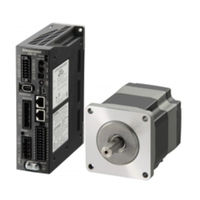
Oriental motor A Step AZ Series User Manual (120 pages)
Motorized Actuator equipped with AZ Series
Brand:
Oriental motor
| Category:
Controller
| Size: 0.8 MB
Table of Contents
Table of Contents
2
Introduction
2
Before Using the Product
6
Operating Manuals
7
Related Operating Manuals
7
How to Use Operating Manuals
7
Overview of the Product
9
Safety Precautions
10
Precautions for Use
12
System Configuration
16
Preparation
17
Checking the Product
17
How to Identify the Product Model
17
Products Possible to Combine
17
Information about Nameplate
18
Names and Functions of Parts
18
Indication of Leds
19
Installation
21
Installation Location
21
Installation Method
21
Connection
23
Connection Example
23
Connecting the Main Power Supply and the Control Power Supply (CN1)
24
Connecting the Ethernet/Ip Cable (CN3, CN4)
26
Connecting the USB Cable
26
Connecting Input Signals (CN5)
26
Noise Elimination Measures
27
Conformity to EMC
28
Setting of IP Address
30
Setting Method of IP Address
30
When Using the IP Address Setting Switch
30
When Setting with Parameters
31
When Setting with DHCP Server
32
Inspection and Maintenance
33
Inspection
33
Warranty
33
Disposal
33
Cable
34
Connection Cables
34
Power Supply Cable
36
Implicit Communication
38
Flow of Implicit Communication
38
Guidance
39
Communication Specifications
42
Implicit Message
43
Implicit Message Format
43
Input Data
44
Output Data
47
Processing Order of Implicit Communication
51
Data Writing
52
Data Reading
53
Example of Execution for Operation
55
Positioning Operation
55
Continuous Operation
56
Direct Data Operation
57
Overview of Direct Data Operation
57
Output Data and Parameters Required for Direct Data Operation
58
Operation Example
61
Timing for Parameter to Update
66
Maintenance Commands
67
Monitor Commands
68
Operation Data R/W Commands
74
Base Address of each Operation Data Number
74
Parameter ID
76
Setting Example
77
Operation I/O Event R/W Commands
78
Base Address of Operation I/O Event
78
Parameter ID for Operation I/O Event R/W Command
78
Protect Release Commands
79
Extended Operation Data Setting R/W Command
80
Parameter R/W Commands
81
Driver Action Simulation Setting Parameter
81
Base Setting Parameter
81
Coordinate Parameters
82
Operation Parameters
82
Direct Data Operation Parameters
82
ABZO Sensor Setting Parameters
83
Mechanism Settings Parameters
83
Initial Coordinate Generation & Wrap Coordinate Parameters
83
JOG/HOME/ZHOME Operation Information Setting Parameters
84
Alarm Setting Parameters
85
Information Setting Parameters
85
I/O Parameters
87
Direct I/O Setting Parameters
90
Remote I/O Setting Parameters
90
Virtual Input Parameters
91
User Output Setting Parameters
92
Driver Mode Setting Parameters
92
Ethernet/Ip Communication Setting Parameters
92
I/O Signals Assignment List
94
Input Signals
94
Output Signals
95
Detection of Communication Errors
98
Communication Timeout
98
IP Address Conflict
98
Alarms
99
Alarm Reset
99
Alarm History
99
Generation Condition of Alarms
99
Alarm List
100
Timing Chart
105
Information
107
Information History
110
Information List
110
Troubleshooting and Remedial Actions
113
Timing Chart
116
Specifications
118
Product Specifications
118
General Specifications
118
Regulations and Standards
119
Advertisement
Related Products
Oriental motor aStep AR Series
Oriental motor AZM26
Oriental motor AZM66
Oriental motor AXH450
Oriental motor AXH015K-A
Oriental motor AXH230KC-A
Oriental motor AXH230KC-GFH
Oriental motor aStep ARM911
Oriental motor ARM69M
Oriental motor AZM911
Oriental motor Categories
Engine
Controller
Fan
Industrial Equipment
DC Drives
More Oriental motor Manuals
Login
Sign In
OR
Sign in with Facebook
Sign in with Google
Upload manual
Upload from disk
Upload from URL