Sign In
Upload
Manuals
Brands
Online USV Manuals
UPS
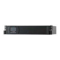
ONLINE XANTO S 2000R
Online USV ONLINE XANTO S 2000R Manuals
Manuals and User Guides for Online USV ONLINE XANTO S 2000R. We have
1
Online USV ONLINE XANTO S 2000R manual available for free PDF download: User Manual
Online USV ONLINE XANTO S 2000R User Manual (222 pages)
Brand:
Online USV
| Category:
UPS
| Size: 3 MB
Table of Contents
Deutsch
3
Benutzerhandbuch
1
Table of Contents
3
Einleitung
6
Abbildung 1: XANTO S Tower und das Optionale Batteriepaket
7
Abbildung 2: XANTO S Rack und das Optionale Batteriepaket
7
Sicherheitswarnungen
8
Montage
10
Überprüfung der Lieferung
10
Auspacken der USV-Anlage
10
Mechanischer Aufbau
11
Überprüfung des Zubehörs
11
Installation des Tower-Modells
11
Elektrische Installation
12
Installation des Rack-Modells
14
Mechanischer Einbau
14
Abbildung 3: Anschließen der Batteriepakete
14
Abbildung 4: Befestigen der Gehäusefront
15
Elektrische Installation
16
Abbildung 6: Entfernen des Kabelauswurfs vom Batteriepaket
17
Abbildung 5: Entfernen der Frontblende von der USV-Anlage
17
Abbildung 7: Entfernen der Frontblende vom Batteriepaket
18
Abbildung 8: Typische Installation Meherer Batteriepakete
19
Inbetriebnahme
20
Betrieb
22
Funktionen auf dem Bedienfeld
22
Abbildung 9: XANTO S Bedienfeld (Modell XANTO S 3000R)
22
Ändern der Sprache
23
Anzeigefunktionen
23
Anwenderprogrammierung
24
Betriebsarten
28
Normalbetrieb
28
Batteriebetrieb
28
Bypassbetrieb
29
Standbybetrieb
30
Starten und Abschalten der USV-Anlage
30
Starten der USV-Anlage
30
Starten der USV-Anlage IM Batteriebetrieb
31
Abschalten der USV-Anlage
32
Betriebsartwechsel der USV-Anlage
32
Einstellen der Energiestrategie
33
Konfigurieren der Bypass-Einstellungen
33
Konfigurieren von Lastsegmenten
34
Konfigurieren der Batterieeinstellungen
36
Konfigurieren der USV-Anlage für Batteriepakete
36
Ausführen der Automatischen Batterietests
37
Konfigurieren des Automatischen Neustarts
37
Spezialfunktionen
38
Frequenzumrichterbetrieb
38
Kommunikation
39
Kommunikationsoptionen
39
RS-232- und USB-Kommunikationsschnittstelle
40
Slot für Schnittstellenkarten
41
Notaus-Funktion (REPO)
42
Abbildung 10: Kommunikationsoptionen (Modell XANTO S 3000R) . 39 Abbildung 11: RS-232 Kommunikationsschnittstelle (DB-9-Stecker) . 40 Abbildung 12: Notaus-Anschluss
43
Abbildung 13: Anschlüsse der Standard-Relais-Schnittstelle
44
Programmierbare Ausgangskontakte
44
Programmierbare Signaleingänge
45
Datawatch Software
46
Wartung
47
Pflege und Wartung von USV-Anlagen / Batterien
47
Lagerung von USV-Anlagen / Batterien
47
Zeitpunkt für das Austauschen der Batterien
48
Batterien Wechseln
48
Austausch der Internen Batterien des Tower-Modells
49
Abbildung 14: Entfernen der Frontblende von der USV-Anlage
50
Austausch des Batteriepaketes des Tower-Modells
52
Austausch der Internen Batterien des Rack-Modells
53
Abbildung 15: Austauschen der Internen Batterien der USV-Anlage . 50 Abbildung 16: Entfernen der Frontblende von der USV-Anlage
53
Austausch des Batteriepaketes vom Rack-Modell
55
Abbildung 17: Austauschen der Internen Batterien der USV-Anlage . 54 Abbildung 18: Entfernen der Frontblende vom Batteriepaket
55
Testen der Neuen Batterien
57
Abbildung 19: Typische Installation Meherer Batteriepakete
57
Entsorgen der Altbatterien oder der USV-Anlage
58
Fehlerbehebung
59
Typische Warn- und Statusmeldungen
59
Stummschalten des Warnsignals
63
Support
63
Technische Daten
64
Spezifikationen der USV-Anlagen
64
Liste der Gerätetypen
64
Gewichte und Abmessungen (Netto)
65
Elektrische Ein- und Ausgänge
66
Batterie
68
Überbrückungszeit
68
Kommunikationsoptionen
69
Umwelt und Sicherheit
69
Rückansichten der USV-Anlagen
70
Abbildung 20: XANTO S 700
70
Abbildung 21: XANTO S 1000 und 1500
70
Abbildung 22: XANTO S 2000
70
Abbildung 23: XANTO S 3000
70
Abbildung 26: XANTO S 3000R
71
Abbildung 24: XANTO S 700R, 1000R und 1500R
71
Abbildung 25: XANTO S 2000R
71
CE Bestätigung
72
Garantie
73
User Manual
75
English
77
Introduction
80
Figure 1: XANTO S Tower and the Optional Battery Module
81
Figure 2: XANTO S Rack and the Optional Battery Module
81
Safety Warnings
82
Inspecting the Shipment
84
Installation
84
Unpacking the UPS System
84
Checking the Accessories
85
Installing the Tower Model
85
Mechanical Installation
85
Electrical Installation
86
Figure 3: Connecting the Battery Modules
88
Installing the Rack Model
88
Mechanical Installation
88
Figure 4: Attaching the Front of the Housing
89
Electrical Installation
90
Figure 5: Removing the Front Cover from the UPS System
91
Figure 6: Removing the Cable Ejection from the Battery Module
91
Figure 7: Removing the Front Cover from the Battery Module
92
Figure 8: Typical Installation of Multiple Battery Modules
93
Commissioning
94
Figure 9: XANTO S Control Panel (Model XANTO S 3000R)
96
Functions on the Control Panel
96
Operation
96
Changing the Language
97
Display Functions
97
User Settings
98
Battery Mode
102
Normal Mode
102
Operating Modes
102
Bypass Mode
103
Standby Mode
104
Starting and Shutting down the UPS System
104
Starting the UPS System
104
Starting the UPS System in Battery Mode
105
Changing Operating Modes of the UPS System
106
Shutting down the UPS System
106
Configuring the Bypass Settings
107
Setting the Power Strategy
107
Configuring Load Segments
108
Configuring the Battery Settings
110
Configuring the UPS System for Battery Modules
110
Configuring the Automatic Restart
111
Performing the Automatic Battery Tests
111
Converter Mode
112
Special Functions
112
Communication
113
Communication Options
113
Figure 10: Communication Options (Model XANTO S 3000R)
113
And USB Communication Interfaces
114
Figure 11: RS-232 Communication Port (DB-9 Connector)
114
Slot for Interface Cards
115
Emergency-Off Function (REPO)
116
Figure 12: Emergency-Off Connection
117
Figure 13: Connections of the Standard Relay Interface
118
Programmable Output Contacts
118
Programmable Signal Inputs
119
Datawatch Software
120
Care and Maintenance of UPS Systems/Batteries
121
Maintenance
121
Storing UPS Systems/Batteries
121
Replacing Batteries
122
When to Replace Batteries
122
Replacing the Internal Batteries of the Tower Model
123
Figure 14: Removing the Front Cover from the UPS System
124
Figure 15: Replacing the Internal Batteries of the UPS System
124
Replacing the Battery Module of the Tower Model
126
Figure 16: Removing the Front Cover from the UPS System
127
Replacing the Internal Batteries of the Rack Model
127
Figure 17: Replacing the Internal Batteries of the UPS System
128
Figure 18: Removing the Front Cover of the Battery Module
129
Replacing the Battery Module of the Rack Model
129
Figure 19: Typical Installation of Multiple Battery Modules
131
Testing the New Batteries
131
Disposing of Old Batteries or the UPS System
132
Troubleshooting
133
Typical Warning and Status Messages
133
Muting the Warning Signal
137
Support
137
List of the Device Types
138
Technical Data
138
UPS Systems Specifications
138
Dimensions and Weights (Net)
139
Electrical Inputs and Outputs
140
Autonomy Time
142
Battery
142
Communication Options
143
Environment and Safety
143
Back Views of the UPS Systems
144
Figure 20: XANTO S 700
144
Figure 21: XANTO S 1000 and 1500
144
Figure 22: XANTO S 2000
144
Figure 23: XANTO S 3000
144
Figure 24: XANTO S 700R, 1000R and 1500R
145
Figure 25: XANTO S 2000R
145
Figure 26: XANTO S 3000R
145
CE Conformity
146
Warranty
147
Manuale Dell'utente
149
Italiano
151
Introduzione
154
Figura 1: XANTO S Tower E Pacco Batterie Opzionale
155
Figura 2: XANTO S Rack E Pacco Batterie Opzionale
155
Avvertenze DI Sicurezza
156
Controllo Della Fornitura
158
Disimballaggio Dell'ups
158
Montaggio
158
Controllo Degli Accessori
159
Installazione del Modello Tower
160
Installazione Elettrica
160
Struttura Meccanica
160
Figura 3: Collegamento Dei Pacchi Batterie
162
Installazione del Modello in Armadio Rack
162
Montaggio Meccanico
162
Figura 4: Fissaggio del Lato Anteriore del Cabinet
163
Installazione Elettrica
164
Figura 5: Rimozione del Pannello Frontale Dal Sistema UPS
165
Figura 6: Rimozione Dell'uscita Cavi Dal Pacco Batterie
165
Figura 7: Rimozione del Pannello Frontale Dal Pacco Batterie
166
Figura 8: Installazione Tipica DI Più Pacchi Batterie
167
Messa in Funzione
167
Figura 9: Quadro DI Comando del Sistema XANTO S (Modello XANTOS 3000R)
170
Funzionamento
170
Funzioni Sul Quadro DI Comando
170
Funzioni DI Indicazione
171
Modifica Della Lingua
171
Programmazione Utente
172
Funzionamento a Batteria
176
Funzionamento Normale
176
Modalità D'esercizio
176
Modalità Bypass
177
Avvio Dell'ups
178
Avvio E Spegnimento Dell'ups
178
Modalità Standby
178
Avvio Dell'ups in Modalità a Batteria
179
Commutazione Della Modalità D'esercizio Dell'ups
180
Spegnimento Dell'ups
180
Configurazione Delle Impostazioni DI Bypass
181
Impostazione Della Strategia Energetica
181
Configurazione Dei Segmenti DI Carico
183
Configurazione Dell'ups Per Pacchi Batterie
184
Configurazione Delle Impostazioni Delle Batterie
184
Configurazione del Riavvio Automatico
185
Esecuzione Dei Test Automatici Delle Batterie
185
Funzioni Speciali
186
Modalità Converter (Convertitore DI Frequenza)
186
Comunicazione
187
Figura 10: Opzioni DI Comunicazione (Modello XANTO S 3000R)
187
Opzioni DI Comunicazione
187
Interfaccia DI Comunicazione RS-232 E USB
188
Slot Per Schede D'interfaccia
189
Funzione DI Arresto D'emergenza Remoto (REPO)
190
Figura 11: Interfaccia DI Comunicazione RS-232 (Connettore DB-9) 188 Figura 12: Porta Per L'arresto D'emergenza
191
Figura 13: Collegamenti Dell'interfaccia Relè Standard
192
Segnalazioni (Contatti) DI Uscita Programmabili
192
Segnalazioni (Contatti) DI Ingresso Programmabili
193
Software Datawatch
194
Cura E Manutenzione Dell' UPS E Delle Batterie
195
Immagazzinamento Dei Sistemi Ups/Delle Batterie
195
Manutenzione
195
Quando Sostituire Le Batterie
196
Sostituzione Delle Batterie
196
Sostituzione Delle Batterie Interne del Modello Tower
197
Figura 14: Rimozione del Pannello Frontale Dall'ups
198
Figura 15: Sostituzione Delle Batterie Interne Dell'ups
198
Sostituzione del Pacco Batterie del Modello Tower
200
Figura 16: Rimozione del Pannello Frontale Dall'ups
201
Sostituzione Delle Batterie Interne Dell'ups in Formato Rack
201
Figura 17: Sostituzione Delle Batterie Interne Dell'ups
202
Figura 18: Rimozione del Pannello Frontale Dal Pacco Batterie
203
Sostituzione del Pacco Batterie Dell'ups in Formato Rack
203
Figura 19: Installazione Tipica DI Più Pacchi Batterie
205
Test Delle Batterie Nuove
205
Smaltimento Delle Batterie Vecchie O Dell'ups
206
Eliminazione Dei Guasti
207
Messaggi DI Avvertimento E DI Stato Tipici
207
Servizio Assistenza
211
Silenziamento del Segnale DI Avvertimento
211
Dati Tecnici
212
Elenco Dei Modelli
212
Specifiche Dei Sistemi UPS
212
Pesi E Dimensioni (Netti)
213
Ingressi E Uscite Elettrici
214
Autonomia
216
Batteria
216
Ambiente E Sicurezza
217
Opzioni DI Comunicazione
217
Figura 20: XANTO S 700
218
Figura 21: XANTO S 1000 E 1500
218
Figura 22: XANTO S 2000
218
Figura 23: XANTO S 3000
218
Viste Posteriori Dei Sistemi UPS
218
Figura 24: XANTO S 700R, 1000R E 1500R
219
Figura 25: XANTO S 2000R
219
Figura 26: XANTO S 3000R
219
Dichiarazione CE
220
Garanzia
221
Advertisement
Advertisement
Related Products
Online USV ONLINE XANTO S 2000
Online USV ONLINE XANTO S 700
Online USV ONLINE XANTO S 1000
Online USV ONLINE XANTO S 1500
Online USV ONLINE XANTO S 3000
Online USV ONLINE XANTO S 700R
Online USV ONLINE XANTO S 1000R
Online USV ONLINE XANTO S 1500R
Online USV ONLINE XANTO S 3000R
Online USV ONLINE XANTO S Series
Online USV Categories
UPS
Power Supply
Switch
Racks & Stands
More Online USV Manuals
Login
Sign In
OR
Sign in with Facebook
Sign in with Google
Upload manual
Upload from disk
Upload from URL