Sign In
Upload
Manuals
Brands
Omron Manuals
Controller
NC1-510000
Omron NC1-510000 Manuals
Manuals and User Guides for Omron NC1-510000. We have
1
Omron NC1-510000 manual available for free PDF download: User Manual
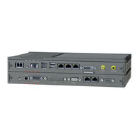
Omron NC1-510000 User Manual (188 pages)
AMR Controller
Brand:
Omron
| Category:
Controller
| Size: 7.96 MB
Table of Contents
Intended Audience
3
Applicable Products
3
Sections in this Manual
5
Table of Contents
6
Manual Information
10
Page Structure
10
Special Information
11
Terms and Conditions Agreement
12
Warranty, Limitations of Liability
12
Application Considerations
13
Disclaimers
14
Safety Precautions
15
Definition of Precautionary Information
15
Symbols
15
Warnings
16
Cautions
18
Precautions for Safe Use
19
Disassembly, Dropping, Mounting, Installation and Storage
19
Wiring
19
Wireless
19
Power Supply Design and Turning ON/OFF the Power Supply
21
Actual Operation
21
Operation
22
General Communications
22
Cleaning, Maintenance and Disposal
22
Precautions for Correct Use
23
Storage, Installation and Mounting
23
Wiring
23
Actual Operation and Operation
24
Battery Replacement
24
SD Memory Cards
24
Regulations and Standards
25
Conformance to EU Directives
25
Conformance to KC Certification
25
Conformance to UL and CSA Standards
26
Software Licenses and Copyrights
26
Related Manuals
27
Related AMR Controller Manual
27
Terminology and Abbreviations
28
Industrial PC Platform
28
Hardware
28
Software
29
Revision History
30
Overview
32
Intended Use
32
Hardware Features
33
ID Information Label
34
Product Configuration
35
System Configurations
37
Configuration for a Mobile Robot
38
Layers and Components
41
Cooling Layer
42
Base Layer
42
Mobile Robot Layer
44
LED Indicators Base Layer
45
PWR LED Indicator
45
ERR LED Indicator
46
HDD LED Indicator
46
RUN LED Indicator
46
LED Indicators Mobile Robot Layer
47
MCU LED Indicator
47
IO LED Indicator
48
DRV LED Indicator
48
CAN LED Indicator
48
Power Button
49
SD Memory Card Slot
50
Cfast Card Slot
51
Connectors Base Layer
52
Power Connector
52
I/O Connector
52
USB Connectors
53
Ethernet Connectors
54
DVI Connector
54
Wifi Connectors
55
Connectors Mobile Robot Layer
56
Line Connector
56
Audio Connector
57
CAN Connector
57
Expansion Connector
58
COMM Connector
58
Ethernet Connectors
59
PLC Safety I/O Connector
60
Spare Parts
61
Accessory Kit
61
Connectors
61
3-10 Optional Hardware
62
Mounting Brackets
62
SD Memory Cards
62
USB Flash Drives
63
Cfast Cards
63
DVI Cables
64
USB Type-A to USB Type-B Cables
64
Power Supply
65
Ups
65
Specifications
67
General Specifications
68
Dimensions and Weight
68
General Electrical Specifications
69
Power Consumption Specifications
70
Power Supply Specifications
71
CPU Specifications
72
Memory Specifications
72
Storage Device Specifications
73
Bracket Specifications
74
Connector Specifications
77
Power Connector Specifications
77
I/O Connector Specifications
78
USB Connector Specifications
82
Ethernet Connector Specifications
83
DVI Connector Specifications
86
Wireless Interface Specifications
87
LINE Analog Audio Connector Specifications
88
AUDIO Optical Audio Connector Specifications
89
CAN Connector Specifications
90
EXPANSION Connector Specifications
91
COMM Connector Specifications
93
PLC Connector Specifications
95
Environmental Specifications
97
Operation Environment Specifications
97
Temperature and Humidity Specifications
98
Recycling Specifications
98
Installation
99
Unpack
100
Unpack Procedure
100
Items Supplied
100
Install Options
103
Mount
104
Installation Method in Control Panels
104
Product Orientation
105
Temperature
106
Humidity
109
Vibration and Shock
109
Atmosphere
110
Electrical Environment
110
Book Mount Procedure
116
Wall Mount Procedure
117
Wire
118
Wiring Warnings and Cautions
118
Ground
118
Wire the Power Connector
125
Wire the I/O Connector
129
Connect
132
Connector Identification
132
Connection Procedure
133
Initial Power on
135
Initial Power on Procedure
135
Install Software
137
Connect UPS
138
Connect UPS Using the USB Connector
139
Connect UPS Using the I/O Connector
141
Create Backup and Repair Data
144
Power on
146
Power on Using the Power Button
146
Power on Using the Power ON/OFF Input
146
Auto Power on
146
Power off
147
Power off Using the Power Button
147
Power off Using the Power ON/OFF Input
148
Forced Power off Using the Power Button
148
Preventive Maintenance
150
Preventive Maintenance Schedule
150
Clean the AMR Controller
151
Corrective Maintenance
152
Warning and Error Messages
152
Replace the Cfast Card
154
A-1 Bios
158
A-1-1 BIOS Overview
158
BIOS Overview
158
BIOS for 7 Th Generation Cpus
160
A-2 DVI Connector Pin Details
176
A-2-1 DVI-I Connector Pin Details
176
DVI-I Connector Pin Details
176
A-3 CAN Connector Pin Details
178
A-4 EXPANSION Connector Pin Details
179
A-5 COMM Connector Pin Details
181
A-6 PLC Connector Pin Details
182
Advertisement
Advertisement
Related Products
Omron NC1-510001
Omron NE1A-SCPU01-V1
Omron NX Series
Omron NX-SL5500
Omron NX-SID Series
Omron Sysmac NX1P2-11 1 Series
Omron NS600
Omron NJ501-R300
Omron NB7W-TW B-V1 Series
Omron sysmac NX102-9 Series
Omron Categories
Blood Pressure Monitor
Controller
Accessories
Switch
Inverter
More Omron Manuals
Login
Sign In
OR
Sign in with Facebook
Sign in with Google
Upload manual
Upload from disk
Upload from URL