Sign In
Upload
Manuals
Brands
OMRON Manuals
Computer Hardware
CP1H-CPU - 05-2006
OMRON CP1H-CPU - 05-2006 Manuals
Manuals and User Guides for OMRON CP1H-CPU - 05-2006. We have
1
OMRON CP1H-CPU - 05-2006 manual available for free PDF download: Operation Manual
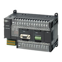
OMRON CP1H-CPU - 05-2006 Operation Manual (669 pages)
CP1H CPU Unit
Brand:
OMRON
| Category:
Computer Hardware
| Size: 17.65 MB
Table of Contents
Table of Contents
8
About this Manual
12
Related Manuals
14
Precautions
20
General Precautions
21
Intended Audience
21
Safety Precautions
21
Operating Environment Precautions
23
Application Precautions
24
Conformance to EC Directives
27
Applicable Directives
27
Concepts
27
Relay Output Noise Reduction Methods
28
Conditions for Meeting EMC Directives When Using CPM1A Relay Expansion I/O Units
29
Section 1 Features and System Configuration
32
Features and System Configuration
32
Features and Main Functions
33
CP1H Overview
33
Features
37
System Configuration
46
Basic System
46
Optional Products
47
Serial Communications
47
System Expansion
48
System Expansion with CJ-Series Units
51
Restrictions on System Configuration
53
Connecting Programming Devices
55
Connecting to a USB Port
55
Connecting to a Serial Port
64
Function Charts
66
Cpu Units
67
Function Blocks
69
Advantages of Function Blocks
69
Overview of Function Blocks
69
Section 2 Nomenclature and Specifications
72
Nomenclature and Specifications
72
Part Names and Functions
73
CP1H CPU Units
73
CP1W-CIF01 RS-232C Option Boards
77
CP1W-CIF11 RS-422A/485 Option Boards
78
Specifications
79
CP1H CPU Units
79
I/O Memory Details
83
I/O Specifications for XA and X CPU Units
84
Input Specifications
86
Output Specifications
89
Built-In Analog I/O Specifications (XA CPU Units Only)
92
I/O Specifications for y CPU Units
94
CPM1A Expansion I/O Unit I/O Specifications
101
CP1H CPU Unit Operation
104
Overview of CPU Unit Configuration
104
Flash Memory Data Transfers
108
Memory Cassette Data Transfers
110
CPU Unit Operation
112
General Flow
112
I/O Refreshing and Peripheral Servicing
113
I/O Refresh Methods
114
Initialization at Startup
116
CPU Unit Operating Modes
117
Operating Modes
117
Status and Operations in each Operating Mode
117
Operating Mode Changes and I/O Memory
118
Startup Mode Setting
118
Power off Operation
119
Overview
119
Description of Operation
120
Instruction Execution for Power Interruptions
120
Computing the Cycle Time
121
CPU Unit Operation Flowchart
121
Cycle Time Overview
122
Functions Related to the Cycle Time
124
Minimum Cycle Time
124
I/O Refresh Times for PLC Units
125
Cycle Time Calculation Example
126
Online Editing Cycle Time Extension
127
I/O Response Time
128
Interrupt Response Times
129
2-7-10 Pulse Output Start Time
131
Serial PLC Link Response Performance
131
2-7-11 Pulse Output Change Response Time
132
Section 3 Installation and Wiring
134
Installation and Wiring
134
Fail-Safe Circuits
135
Installation Precautions
136
Installation and Wiring Precautions
136
Mounting
138
Mounting in a Panel
138
Connecting CPM1A Expansion Units and Expansion I/O Units
142
Mounting Height
142
Connecting CJ-Series Units
144
DIN Track Installation
145
Wiring CP1H CPU Units
147
Wiring Power Supply and Ground Lines
148
Wiring Built-In I/O
150
Wiring Safety and Noise Controls
154
Wiring Methods
155
Example I/O Wiring for X and XA CPU Units
155
Example I/O Wiring for y CPU Units
157
Pulse Input Connection Examples
158
Pulse Output Connection Examples
159
Wiring Built-In Analog I/O (XA CPU Units Only)
161
CPM1A Expansion I/O Unit Wiring
164
Section 4 I\/O Memory Allocation
170
I/O Memory Allocation
170
Overview of I/O Memory Area
171
I/O Memory Area
171
Overview of the Data Areas
173
Clearing and Holding I/O Memory
177
Hot Start/Hot Stop Functions
177
I/O Area and I/O Allocations
179
Overview
179
Allocations to Built-In General Purpose I/O on the CPU Unit
180
Allocations to CP1H y CPU Units (12 Inputs/8 Outputs)
181
Allocations to CPM1A Expansion Units and Expansion I/O Units
181
Expansion Units
183
I/O Allocation Examples
183
Built-In Analog I/O Area (XA CPU Units Only)
184
Data Link Area
185
CPU Bus Unit Area
186
Special I/O Unit Area
187
Serial PLC Link Area
188
Devicenet Area
189
Internal I/O Area
190
Holding Area (H)
190
Auxiliary Area (A)
191
4-12 TR (Temporary Relay) Area
192
4-13 Timers and Counters
193
Timer Area (T)
193
Counter Area (C)
194
Data Memory Area (D)
195
4-13-3 Changing the BCD or Binary Mode for Counters and Timers
195
4-15 Index Registers
197
4-15-1 Using Index Registers
200
Precautions for Using Index Registers
202
4-16 Data Registers
204
4-17 Task Flags
206
4-18 Condition Flags
206
4-19 Clock Pulses
208
Section 5 Basic Cp1H Functions
210
Basic CP1H Functions
210
Interrupt Functions
211
Overview of CP1H Interrupt Functions
211
Input Interrupts (Direct Mode)
215
Input Interrupts (Counter Mode)
220
Scheduled Interrupts
223
High-Speed Counter Interrupts
226
High-Speed Counters
235
External Interrupts
235
Overview
235
High-Speed Counter Specifications
236
Procedure
242
PLC Setup
243
High-Speed Counter Terminal Allocation
243
Pulse Input Connection Examples
246
Ladder Program Example
247
Additional Capabilities and Restrictions
250
Pulse Outputs
255
Overview
255
Pulse Output Specifications
257
Pulse Output Terminal Allocations
259
Pulse Output Patterns
265
Origin Search and Origin Return Functions
280
Related Auxiliary Area Flags
295
Origin Return
299
Pulse Output Procedures
301
Instructions Used for Pulse Outputs
303
Variable Duty Factor Pulse Outputs (PWM(891) Outputs)
314
5-3-10 Example Pulse Output Applications
315
Cutting Long Material Using Fixed Feeding
322
Quick-Response Inputs
346
Analog I/O (XA CPU Units)
349
Advanced Functions
362
Serial Communications
363
No-Protocol Communications
365
Modbus-Rtu Easy Master Function
367
Communications: Smart Active Parts and Function Blocks
370
Serial Plc Links
371
N Nt Links
379
Host Link Communications
380
Analog Adjuster and External Analog Setting Input
384
External Analog Setting Input
385
7-Segment LED Display
386
Battery-Free Operation
388
Memory Cassette Functions
390
Mounting and Removing a Memory Cassette
391
Operation Using the CX-Programmer
393
Memory Cassette Data Transfer Function
394
Program Protection
398
Read Protection
398
Write Protection
401
Protecting Program Execution Using the Lot Number
403
Failure Diagnosis Functions
405
Simulating System Errors
407
Output off Bit
408
Clock
409
Using CPM1A Expansion Units and Expansion I/O Units
412
Connecting CPM1A Expansion Units and Expansion I/O Units
413
Analog Input Units
414
Analog Input Signal Ranges
416
Analog Output Units
423
Analog Output Signal Ranges
425
Analog I/O Units
431
Cpm1A-Mad11 Analog I/O Units
441
Temperature Sensor Units
454
Main Specifications
455
Compobus/S I/O Link Units
469
Operating Procedure
472
Devicenet I/O Link Units
475
Program Transfer, Trial Operation, and Debugging
482
Program Transfer
483
Trial Operation and Debugging
483
Forced Set/Reset
483
Differential Monitoring
484
Tracing Data
487
Troubleshooting
490
Error Classification and Confirmation
491
Troubleshooting
496
Error Processing Flowchart
497
No Operation When Power Is Supplied
497
Fatal Errors
498
Cpu Errors
503
Non-Fatal Errors
503
Other Errors
507
Error Log
508
Troubleshooting Unit Errors
509
Inspection and Maintenance
512
10-1 Inspections
513
Inspection Points
513
Unit Replacement Precautions
514
10-2 Replacing User-Serviceable Parts
515
Standard Models
520
Dimensions Diagrams
528
Auxiliary Area Allocations by Function
536
Cpu Unit Settings
536
Initial Settings
536
Data Tracing
542
Comment Memory
543
Auxiliary Area Allocations by Address
556
Memory Map
602
Connection Methods
604
Connections to Serial Communications Option Boards
604
Connection Examples
622
F Connections to Serial Communications Option Boards
628
PLC Setup
630
Background Execution Settings
631
Input Constant Settings
633
Pulse Output 0 Settings
644
Pulse Output 1 Settings
647
Index
660
Revision History
666
Advertisement
Advertisement
Related Products
Omron SYSMAC CP1L-M60DT-A
Omron SYSMAC CP1L-L20DT1-D
Omron CP1E-E14SDR-A
Omron CP1E-E30SDR-A
Omron SYSMAC CP1E-E10DT1-A
Omron SYSMAC CP1E-E14DR-A
Omron CP1E-N60S1DT-D
Omron CP1E-N60S1DT1-D
Omron SYSMAC CP1E-NA20DT1-D
Omron SYSMAC CP1E-NA20DT-D
OMRON Categories
Blood Pressure Monitor
Controller
Accessories
Switch
Inverter
More OMRON Manuals
Login
Sign In
OR
Sign in with Facebook
Sign in with Google
Upload manual
Upload from disk
Upload from URL