Sign In
Upload
Manuals
Brands
Omron Manuals
Controller
CP1E-N**S*D Series
User Manuals: Omron CP1E-N**S*D Series Logic Controller
Manuals and User Guides for Omron CP1E-N**S*D Series Logic Controller. We have
1
Omron CP1E-N**S*D Series Logic Controller manual available for free PDF download: User Manual
Omron CP1E-N**S*D Series User Manual (326 pages)
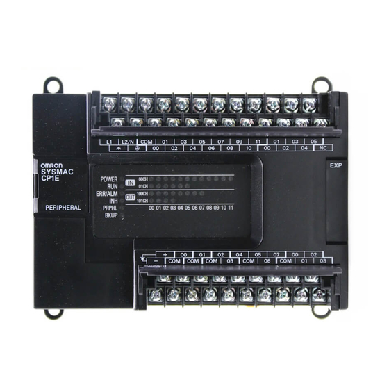
SYSMAC CP Series CP1E CPU Unit Hardware
Brand:
Omron
| Category:
Controller
| Size: 12 MB
Table of Contents
CP1E CPU Unit Manuals
6
Manual Structure
9
Table of Contents
12
Terms and Conditions Agreement
16
Safety Precautions
18
Precautions for Safe Use
23
Operating Environment Precautions
26
Regulations and Standards
27
Related Manuals
28
Overview and Specifications
29
CP1E Overview
30
Overview of Features
30
Features
31
Basic Operating Procedure
36
Specifications
37
General Specifications
37
Characteristics
38
Functional Specifications
40
Difference between E/N/NA-Type and E/NS(1)-Type
42
Basic System Configuration and Devices
45
Basic System Configuration
46
Basic System Configuration Using an E(S)-Type CPU Unit
46
Basic System Configuration Using an N/NA(S)-Type CPU Unit
47
CPU Units
48
CPU Unit Models
48
Optional Products
53
Unit Versions of CPU Units
55
Expansion I/O Unit or Expansion Unit
57
Expandable CPU Units
57
Connection Methods
57
Maximum Number of I/O Points for an Expansion I/O Unit or Expansion Unit
57
Expansion Unit
57
Expansion I/O Units and Expansion Units
58
Restrictions on System Configuration
60
Unit Current Consumption and External Power Supply Capacity
62
External Power Supply Capacity When Expansion I/O Units or Expansion Units Are Connected
62
External Power Supply Capacity When Expansion I/O Units or
62
Expansion Units Are Connected
62
Current Consumption
63
Part Names and Functions
68
CPU Units
68
E10/14/20(S) or N14/20 CPU Units
68
E30/40/60(S), N30/40/60(S) or NA20 CPU Units
73
Common I/O Specifications
79
Optional Serial Communications Port for N/NA(S)-Type CPU Units
85
Analog Option Board for N/NA-Type CPU Units
90
Expansion I/O Units
94
Expansion Input Unit
94
Expansion Output Units
94
Expansion Output Units
95
Expansion I/O Units
95
Expansion I/O Units
97
I/O Specifications
99
Applicable Programming Devices for CP1E
104
Applicable Programming Devices
104
CX-Programmer
105
Operating Environment and System Configuration
106
Features of the CX-Programmer
106
Installing the Software
109
Connecting by USB
110
Installing the USB Driver
111
Connection Method with a Serial Port
118
Installation and Wiring
119
Fail-Safe Circuits
120
Installation
121
Installation Location
121
Unit Arrangement
124
Installation
125
Connecting Expansion I/O Units and Expansion Units
130
Wiring
132
Wiring Procedure
132
Wiring Power Supply and Ground Lines
132
I/O Wiring
135
Wiring Safety and Noise Controls
139
Relay Output Noise Reduction Methods
140
Troubleshooting
143
Troubleshooting CPU Unit Errors
144
Errors and Remedies
144
Checking Errors
144
Checking Detailed Status
145
Reading Error Log Information
145
Types of Errors
147
Error Processing Flowchart
148
No Operation When Power Is Supplied
149
Fatal Errors
149
CPU Errors
153
6-1-10 Non-Fatal Errors
154
6-1-11 Other Errors
156
Troubleshooting Unit Errors
157
Inputs
157
Outputs
158
Built-In Analog
159
CX-Programmer Connection
160
Maintenance and Inspection
161
Periodic Maintenance and Inspection
162
Tools Required for Inspections
162
Periodic Inspection
162
Inspection and Maintenance
163
Unit Replacement Precautions
164
Replacing the Battery in N/NA(S)-Type CPU Units
165
Analog Input Units
170
Overview
170
Part Names and Functions
170
Specifications
171
Flow of Operation
175
Analog Input Units
175
Analog Output Units
183
Overview
183
Part Names and Functions
183
Specifications
184
Flow of Operation
188
Analog Output Units
188
Analog I/O Units
195
CP1W-MAD11 Analog I/O Units
195
Overview
195
Specifications
196
CP1W-MAD42/CP1W-MAD44 Analog I/O Units
208
Temperature Sensor Units
224
CP1W-TS1/TS2 Temperature Sensor Units
224
CP1W-TS003 Temperature Sensor Units
239
TS004 Temperature Sensor Units
249
Compobus/S I/O Link Units
260
Overview
260
Part Names and Functions
260
Specifications
262
Flow of Operation
262
Appendices
265
Dimensions
266
A-1-1 CPU Units
266
CPU Units
266
A-1-2 Option Boards
269
A-1-3 Expansion I/O Units
272
A-1-4 Expansion Units
274
Wiring Diagrams
276
A-2-1 CPU Units
276
CPU Units
276
A-2-2 Expansion I/O Units
285
Expansion Units
285
Expansion Units
292
A-2-4 Serial Communications
303
Wiring for Serial Communications
308
A-3-1 Recommended RS-232C Wiring
308
Recommended RS-232C Wiring
308
A-3-2 Recommended RS-422A/485 Wiring
311
Recommended RS-422A/485 Wiring
311
Converting the Built-In RS-232C Port to RS-422A/485
314
Reducing Electrical Noise for External Wiring
317
Index
319
Revision History
323
Advertisement
Advertisement
Related Products
OMRON CP1E INTRODUCTION
Omron CP1E-E**D Series
Omron CP1E-NA**D Series
Omron CP1E-N**D Series
Omron CP1E-E**SD Series
Omron CP1E-N40D Series
Omron CP1E-N30D Series
Omron CP1E-N20D Series
Omron SYSMAC CP1E-N S D Series
Omron Sysmac CP1H-X40DRA
Omron Categories
Blood Pressure Monitor
Controller
Accessories
Switch
Inverter
More Omron Manuals
Login
Sign In
OR
Sign in with Facebook
Sign in with Google
Upload manual
Upload from disk
Upload from URL