Sign In
Upload
Manuals
Brands
Okuma Manuals
Control Unit
OSP 5000
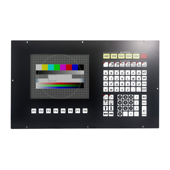
Okuma OSP 5000 Spindle Control Panel Manuals
Manuals and User Guides for Okuma OSP 5000 Spindle Control Panel. We have
1
Okuma OSP 5000 Spindle Control Panel manual available for free PDF download: Electrical Maintenance, Training Manual
Okuma OSP 5000 Electrical Maintenance, Training Manual (287 pages)
Lathe/Machining center
Brand:
Okuma
| Category:
Control Unit
| Size: 5 MB
Table of Contents
Terms and Acronyms
9
Table of Contents
13
Safety Precautions
17
Checks before Turning on Power
17
Precautions to Observe When Using a Chuck
17
Checkup Around the Machine
18
Precautions for Machine Operations
18
Setup
19
Workpiece Loading and Unloading
19
Machine Centers
19
At the End of the Day
20
When a Problem Occurs
20
Other General Precautions
20
Machine Definition
33
Machine Tool
35
Numerical Control Machine
35
Computerized Numerical Control Machine
35
Microprocessor
36
Memory
36
Permanent Storage
36
Long-Term Storage
37
Temporary Storage
37
Servo System
38
I/O Devices
38
Tape Reader
38
Disk Drives
39
RS-232 Interface
39
External Switches
39
Lathe
40
Machining Center
41
Vertical Machining Center
41
Horizontal Machining Center
42
Travelling Column Type Horizontal Machining Center
43
Double Column Machining Center
44
Grinder
45
Work Coordinate System for OD Grinding
46
Wheel Coordinate System for OD Grinding
47
Wheel Coordinate System for ID Grinding
47
Machine Operation
48
Basic Construction of the Operation Panels
50
NC Operation Panel
50
Functions Available When the AUTO Mode Key Is Pressed
51
MDI
53
Manual
53
Actual Position
54
Part Program
54
Block Data
55
Check Data
55
Tool Data
56
Edit AUX
57
Zero Set
58
Parameter
59
Auto Mode
60
Functions Available When the MDI Mode Key Is Pressed
63
Functions Available When the MANUAL Mode Key Is Pressed
63
Actual Posit, Part Program, Block Data and Check Data Menus
64
Data Setting Mode Keys (Tool Data, Edit Aux, Zero Set and Parameter)
66
NC Status Display Lamps
70
Mode Selection Keys
70
Data Setting Mode
70
Operation Mode
71
Character Keys
71
Numeric Keypad
71
LATHE Machine Operation Panel
72
Cursor Keys
72
Page Keys
72
Turret Keys
72
Pulse Handle
73
Spindle
73
Spindle Override
73
Coolant
73
Spindle Gear
74
Load Monitor
74
Tool Index
74
Rev.
74
Lighting
75
Single Block
75
Block Delete
75
Individual Mode
75
Stroke End Limit Cancel/Load Mode Panel
76
Inter Lock
76
CRT Display
76
Sequence Restart
76
Machining Center Machine Operation Panel
77
Orientation
77
Cw
77
Release
77
Rev. 8-21-01
77
Jog Speed
78
Freedrate
78
Oil Mist
78
Oil Hose
78
NC Panel
79
NC Operation
79
ATC Operation
80
APC Operation
81
Pendant Operation Panel
82
Optional Panel
82
Hour Meter
82
Operation End Mode
82
Control On/Off
83
Operational Panel above Tape Reader View
87
ATC Magazine Operation Panel View
88
Manual Tool Change Operation
88
Check Panel View
88
MDI Operation
89
Rev.
89
Construction
90
Power Supplies
92
If the Power Source Inductance Is too High
92
Rev.
94
OPUS 5000/5020 Power Supply Unit
96
Alarm and CPU Status Led’s Located on the Control Rack
98
Printed Circuit Boards
98
Rev. 8-21-01
98
Main Processor Board
99
Bubble Memory
99
Ram
100
Different Board Configurations
102
Main Card 13 (A911-1521) RS-232 Card
103
Main Card 15 (A911-1526)
103
Main Card 16 (A911-1516)/Main Card 17 (A911-1517)
103
CRP-IIC (A911-1692) or (A911-1693)
103
Serial if
104
CRP 9 (A911-1580) - CRT Processor Board
104
SVP-IID - Servo Processor Board
104
SPC1 (A911-1534) - Additional 1 Axis Card
105
SPC2 (A911-1535) - Additional Pulse Handle Card
105
EC Board (A911-1120) - Electrical Control Board
105
ECP Board IIA - Electrical Control Processor Board
105
ECP Card 2 (A911-1142) - Expansion Card
106
ECP Card 3 (A911-1143) - Expansion Card
106
ECP Card 4-II (A911-1544) - Expansion Card
106
FDC II BOARD (A911-1703) - Floppy Disk Control Board
106
RS Board (A911-125) - RS-232C Interface Board
107
CCP Board (A911-1594) - Communication Control Processor Board
107
CCPC2 Card (A911-1596) - Signal Converter Card
107
TCC-A (A911-1598)/TCC-B (A911-1599) - Turret Control Card
107
EC I/O Rack
108
Fieldnet I/O Unit
109
Fiber Opitic Cable Part Numbers
110
How to Troubleshoot a Fiber Optic Cable
111
Servo Systems
112
Axis Drives
112
Ldu 600
112
Ldu Tr
113
Bdu
114
Description of Led’s on BDU Style DCPS
114
Led’s on the SVC Board of a BDU-A Type Drive Amplifier
115
Description of Led’s on SVC-1 Board of a BDU-D Drive Amplifier
116
Bld
117
Description of Led’s on BLD-A Type Drive Amplifier
117
Bliid
119
Description of Led’s on BLIID-A Type Drive Amplifier
119
Speed and Position Feedback
119
Led’s on Lower Right Side of the SVC-1Board on BL-IID Type D Drive
121
Spindle Drives
123
Diagnosing a Spindle Drive Alarm
126
Feedback Devices
127
Tachometer
127
Absolute Position Encoder
128
Procedure for Replacing Absolute Position Encoders
128
Removing Encoder from Motor
128
Removing the Encoder from the Motor Shaft
129
Installing the Encoder to the Motor Shaft
129
Mpr
130
Inductosyn
130
Connecting the Encoder Input/Output (Ribbon Cable) Connector
130
VAC Resolver
131
Pulse Generators
131
TCC Resolver
132
Diagnostics
133
Actual Position
135
Machining Center Data
136
Block Data Soft Key
137
Check Data Soft Key
140
Axis
140
EC I/O’s
141
EC Extend I/O’s
141
Panel I/O’s
142
Spec Code
142
Machine Code
142
Alarm Message List
142
NC I/O’s
143
Machine I/O’s
143
NC Spec Table
143
MC Spec Table
143
NC Axis Data
144
Machine Axis Data
144
Alarm List
144
System Variables
144
Alarms
145
Chart Showing the Different Numbering Systems
146
Description of the Different Types of Alarms the Control Can Gener-Ate
147
What Appears on the Screen When a CPU Level Alarm Occurs
148
Display Format of CPU Alarms (Bus Error)
149
BUS Error
150
Access Address (MB II B)
151
Access Address (MB II, MB II A)
152
Access Address (MB) (OSP5000)
153
Display Format of Alarm P, A, B, C and D
155
Alarm Codes
156
How to Check Alarm Contents
156
Peripheral Processor Start
159
SVP Start
159
Timing Generator Stop
161
Tool Number Input
162
Servo Amp
164
Collete Unclamp
165
Turret Index Control Abnormal
165
Alarm Table - Alarm a
166
Spindle Rotation Interlock
167
Probable Faulty Locations
171
Travel Limit over
172
Axis Drive Unit
173
Sequence Count over
173
ATC System Condition
174
Parameters
175
User Parameter Overview
177
Chuck/Tailstock
177
Setting Stroke End Limits
178
Common Variable Info
178
System Parameter Overview
178
Backlash
179
PR Zero Offset Overview
179
Stroke Comp
179
Rapid/Accel Rapid
179
Jog Feed
180
Accel Jog Feed
180
Torque
180
Turret Offset
180
PR Zero Offset
181
Optional Parameter (Long Word)
181
Optional Parameter (Word)
181
Optional Parameter (Bit)
181
Spindle Control Parameter
182
Common Variable
183
User Parameter
183
G/M Code Macro
183
MC User Parameter (Long Word)
183
MC User Parameter (Word)
184
MC User Parameter (Bit)
184
MC System Parameter (Long Word)
184
MC System Parameter (Word)/Nc Optional Parameter (Long Word)
184
NC Optional Parameter (Word)
185
NC Optional Parameter (Bit)
185
Input Unit System
185
System Parameter
185
Setting Zero Offset
186
In Position
186
Zero Offset
186
In Position (H)/SWL HD
187
Barrier (Y,Z)
187
Encoder Offset
187
Home Position Movement Order
187
Inductosyn Offset/Pitch Comp Span/Pitch Point
188
Pitch Error Compensation
188
NC Hour Meter/Power on Time/Nc Running Time
188
Spindle Revolution Time/Cutting Time
188
NC Work Counter
189
Spindle Control Parameter Info
189
External Input Time
189
Software
190
OSP Data Management Card
192
Option Features
192
Option Specification
192
Type of Control Software
193
OSP Management Data Card
194
Type of Control Soft (NC Software)
194
Type of Control Soft (EC Software)
194
Optional Features (NC Software)
194
Optional Features (EC Software)
195
NC-EC Options
195
System
195
Motor/Drive Unit/Position Encoder
195
NC/EC Options
196
Different Methods of Saving Files on Lathes
197
Initializing a Diskette
198
Backing up Part Programs
199
Lathes
199
Special Notes for W-Axis and LT Machines
200
W-Axis Machines
200
To Backup Parameters through Centers with Software 709BF and Higher
201
Reloading the Parameters
202
Tape Format Table
203
Machining Centers
213
Loading Software
213
5020M D-Disk Procedure
215
Schematic Symbols
218
Lathe Schematics
231
Machining Center Schematics
233
Table of Composition Drawings
237
Internal Layout of Control Enclosure
240
External View or Pendant Box
241
Internal Layout of Pendant Box
242
General System Figure of Machine Mounted
243
I/O Card and Gray Code List
244
OSP 502OM CNC System Configuration
245
Power Supply System Diagram
246
Power Supply Circuit Diagram
247
Control Power Circuit
250
Circuit Diagram of NC Control Power
253
Circuit Diagram of Power between Unit
254
Circuit Diagram of Spindle Motor
255
Motors Circuit
256
Circuit Diagram of Axis Drive Unit
257
Servo System Diagram
258
Circuit Diagram of X-Axis Drive Unit
259
Circuit Diagram of Y-Axis Drive Unit
260
Circuit Diagram of Z-Axis Drive Unit
261
Circuit Diagram of A-Axis Drive Unit
262
Circuit Diagram of SVP II-1 Control
263
Circuit Diagram of SVP II-2 Control
264
Circuit Diagram of NC Operation Panel
265
Panel Control Input Circuit Diagram of Manual Operation Panel
266
Panel Control Output Circuit Diagram of Manual Operation Panel
271
Circuit Diagram of Panex Bus Line
273
Panex Bus Line Circuit
274
Circuit Diagram of Operation Panel
275
ECP Bus Line Circuit Diagram
276
EC Control Input
277
EC Control Output
280
ECP Control Circuit (MG Axis)
284
Tape Reader/Winder Loading Circuit
285
PG PHD SP Control Circuit Diagram
286
Advertisement
Advertisement
Related Products
Okuma OSP-U100M
Okuma OSP-U10M
Okuma OSP 5020
Okuma OSP-P200L
Okuma OSP-P20L-R
Okuma OSP-P20L
Okuma OSP-P200L-R
Okuma OSP-E100
Okuma OSP-E10
Okuma OSP-P200
Okuma Categories
Control Unit
Control Systems
Controller
Robotics
Lathe
More Okuma Manuals
Login
Sign In
OR
Sign in with Facebook
Sign in with Google
Upload manual
Upload from disk
Upload from URL