Sign In
Upload
Manuals
Brands
OBR Manuals
Power distribution unit
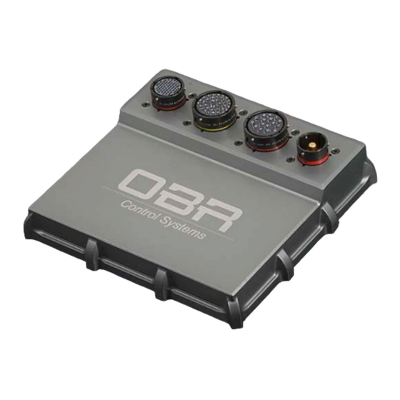
PCM2
OBR PCM2 Power Distribution Module Manuals
Manuals and User Guides for OBR PCM2 Power Distribution Module. We have
1
OBR PCM2 Power Distribution Module manual available for free PDF download: Installation And User Manual
OBR PCM2 Installation And User Manual (92 pages)
Power Control Module
Brand:
OBR
| Category:
Power distribution unit
| Size: 4 MB
Table of Contents
Table of Contents
2
1 Introduction
6
2 Hardware
8
3 Software Installation
9
Software Installation from Web-Download
9
PC Software and Firmware Releases
9
Connection to System
9
Wiring Harness
9
4 Main Menu
10
File
10
Product
10
Device
10
Read
10
Write
10
Reset
11
Firmware
11
Manual Output Mode
11
Automatic Output Mode
11
Manual Output Mode, Keep Current States
11
Get Time
11
Set Time
11
Reset Output Counters
11
Get Firmware Checksum
11
Interface
12
Options
12
Reset Display
12
Sync Time Automatically
12
User
12
Help
12
5 Functions
13
Overview
13
Units
13
Event Handling
13
Event Type
13
Input Follow
13
Input Toggle
14
AND Gate
14
OR Gate
14
NOR Gate
14
XOR Gate
14
NOT Gate
15
Flash
15
Delay Input on
15
Delay Input off
15
Counter Increment
15
Counter Decrement
15
Reset
15
Clock
16
Always on
16
Tri-State Output
16
Wiper Output
16
Event Flash
16
Event Delay on
16
Event Delay off
16
Event Wiper
17
Event Name
17
Source Input
17
Fault Status
17
Turn on / Turn off
17
Event 1 / 2 / 3 / 4 / 5
17
Time (Ms)
18
CAN Inputs - Lost CAN Action
18
CAN Lost Timer
18
Start State
18
Output
18
Multiplier
18
Counter
18
Clock
18
Miscellaneous
19
Special Functions
19
Special Function on
19
Special Function off
19
Counters
20
Increment Action
20
Decrement Action
21
Status
21
Warning Light Status
21
Events Monitor
22
Output Diagnostic
22
6 Compare Two Calibration Files
24
7 User Access Rights
25
Change User
25
Default Passwords
25
Show User Params
25
Import and Export of User Access Rights
26
8 Inputs
27
Digital Inputs
27
Pin Configuration Digital Inputs
27
Analogue Inputs
28
Pin Configuration Analogue Inputs
29
CAN Inputs
30
CAN Overview
30
CAN Channel Editing
30
CAN Row Counts
34
Pin Configuration for CAN Ports
34
9 Outputs
35
Tri-State
35
Pin Configuration Tri-State Outputs
35
Low Power Outputs
36
Parallel Coupling
37
Pin Configuration Low Power Outputs
38
Low Power PWM Outputs
39
Half Bridge - Full Bridge
39
Current Draws
39
Pin Configuration Low Power PWM Outputs
42
High Power Outputs
43
Pin Configuration High Power Outputs
44
High Power PWM Outputs
45
Half Bridge - Full Bridge
45
Current Draws
45
Pin Configuration High Power PWM Outputs
48
Very High Power
49
Pin Configuration very High Power Outputs
50
Wiper Outputs
51
Pin Configuration Wiper Outputs
52
Sensor Supplies
53
Pin Configuration 5 Volt VREF Outputs
53
Warning Light
53
Fault Reset
53
Pin Configuration Warning Light Output
53
10 Visualisation
54
Digital Inputs
54
Analogue Inputs
54
CAN Inputs
55
Events
55
Outputs
55
11 Can Bus
56
Data Bus
56
CAN Bus Name
56
CAN Bus Speed
56
CAN Maximum Identifiers
56
Termination
57
Correctly Terminated CAN Bus
57
Incorrectly Terminated CAN Bus
58
Error Report
59
CAN Bus Identity
59
CAN Monitor
59
CAN Export
60
Configuration of Export Channels
60
Definition of Export Bytes
61
CON" - Constant Value
61
DS" - Digital Input Status
61
AL" - Analogue Input LSB
61
AM" - Analogue Input MSB
61
OS" - Output on or off Status
61
OCL" - Output Current Low Byte
61
OCM" - Output Current MID Byte
61
TO" - Output Tri-State Voltage
62
OFL" - Output Fault Status LSB
62
VVL" & "VVM" - Vehicle Battery Voltage
62
EVL" & "EVH" - Event Status
63
OCH" - Output Current Top Byte
63
OCL2" - Output Current LSB Byte (Ma/2)
63
OCM2" - Output Current MSB Byte (Ma/2)
63
OCL4" - Output Current LSB Byte (Ma/4)
63
OCM4" - Output Current MSB Byte (Ma/4)
63
OCS" - Output Current Single Byte (A)
63
TP" - Temperature Degrees Celcius
63
VC" - Vehicle Current (A)
63
PFL" - PWM Frequency LSB
63
PFM" - PWM Frequency MSB
64
PDC" - PWM Duty Cycle
64
CIL" - CAN Input LSB
64
CIM" - CAN Input MSB
64
CAN Bus Export with Row Count
65
12 LIN Bus - Wiper Motor Control
66
13 Serial Link
68
14 Membrane Switch Panel
69
Software Installation
69
Connection to System
69
Main Menu
70
File
70
Device
70
Firmware Update
70
Interface
70
Help
70
Switches
71
Position and Numbering
71
Switch Name
71
Mode
71
Initial
71
Max
71
New / Leg
71
Press / Release
71
Green Led's
72
Red Led's
72
Extra / Group
72
Status
72
CAN Bus
73
Standard CAN Protocol - Transmit from MSP
73
Standard CAN Protocol - Receive Switch Status from PCM2
75
Standard CAN Protocol - Receive Fault Status from PCM2
76
Speed / Termination / PCM Select
77
Panel Transmit
77
Panel Receive
77
CAN Bus Export
79
Miscellaneous Functions
81
CAN Bus Monitor
81
15 Steering Wheel Controller
83
16 PCM2 Pin Configuration
86
Connector 1 - Battery Power Supply
86
Connector 2 - High Power Outputs
86
Connector 3 - Low Power Outputs
87
Connector 4 - Signal and Inputs
88
17 Specifications
90
Inputs
90
Outputs
90
Very High Power Channels
90
High Power Channels
90
High Power PWM Channels
90
Low Power Channels
90
Low Power PWM Channels
90
Wiper Channels
90
Sensor Supplies & Warning Light
91
Tristate Supplies
91
Maximum Current Rating
91
Temperatures
91
Communication
91
Power Supply
91
Dimensions
92
Advertisement
Advertisement
Related Products
OBR Categories
Power distribution unit
More OBR Manuals
Login
Sign In
OR
Sign in with Facebook
Sign in with Google
Upload manual
Upload from disk
Upload from URL