Sign In
Upload
Manuals
Brands
NSK Manuals
Engine
Megatorque PS Series
NSK Megatorque PS Series Manuals
Manuals and User Guides for NSK Megatorque PS Series. We have
1
NSK Megatorque PS Series manual available for free PDF download: User Manual
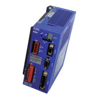
NSK Megatorque PS Series User Manual (370 pages)
MOTOR SYSTEM (EDC Driver Unit System)
Brand:
NSK
| Category:
Engine
| Size: 4 MB
Table of Contents
Table of Contents
11
1 Introduction
15
Notes for Users
15
Notes for Safety
15
Precautions for Use
15
Interchangeability of Motor and Driver Unit
19
Terminology
20
2 Specifications
21
System Configuration
21
Control Mode
21
Examples of System Configuration
22
Referebce Number and Coding
24
PS Series Megatorque Motor
24
EDC Driver Unit for PS Series Megarotque Motor
24
Name of Part
25
PS Series Megatorque Motor
25
EDC Driver Unit
26
Handy Terminal
28
Motor and EDC Driver Unit Combinations
29
Cable Set
30
Handy Teminal
30
Motor Specifications
31
PS Series Megatorque Motor
31
Axial Load and Moment Load
32
External Dimensions
33
PS Series Megatorque Motor
33
EDC Driver Unit
34
Cable Set
36
Flexible Cable
36
Driver Unit Specifications
37
RS-232C Interface Specifications
39
CN1: RS-232C Serial Communication Connector
39
CN1 Pin^out
39
CN1 Signal List
39
Specifications of Control Input/Outputinter Facing
40
CN2: Control Input/Output Signsl Connector
40
CN2 Pin-Out
41
CN2 Signal List
42
CN2 Interfacing
45
General Input Signal
45
Pulse Train Input Signal
46
Output Signal
47
Position Feedback Signal Output
47
5, Analog Monitor Output
48
CN3: Resolver Cable Connector
49
CN3 Pin-Out
49
CN3 Signal List
49
CN4: Motor Connector
50
CN4 Pin-Out
50
CN4 Signal List
50
CN5: Connector for Power Supply
51
CN5 Pin-Out
51
CN5 Wiring Diagram
51
3 Unpacking, Installation and Wiring
53
Unpacking
53
Receiving Check
53
Motor and EDC Driver Unit Combinations
53
Installation
54
Motor Mounting
54
Environmental Conditions of Motor
54
Motor Installation
54
Confirmation of Use Conditions
55
Coupling Load to Motor
55
Dummy Inertia
55
Installation of Driver Unit
56
Wiring
57
Connecting Power
58
Ground Connection
59
Connector Wiring
60
Wiring Example (CN2)
61
Precautions before Power on
62
Points to be Checked When Power on
63
Polarity Setting (Normally Open Contact and Normally Closed Contact)
64
Power on and Servo on
65
4 Handy Terminal Communication
67
Cehck on Handy Terminal
68
Input of the Password
69
Reset to Shippong Set
69
Monitoring Parameters by a Group
70
Monitoring Parameters Altered from Shipping Set
70
Monitoring Current Status
71
Inputting a Command While Monitoring Multiple Conditions
71
5 Tuning
73
Tuning Flowchart
73
Tuning Level 1: Automatic Tuning
74
Precaustions for Automatic Tuning
75
Initilization of Servo Parameters
76
Automatic Tuning
77
Trial Running
79
Tuning Level 2: Servo Gain Tuning
81
Input of Load Inertia
81
Minor Tuning of Servo Gains
82
Tuning Level 3: Manual Tuning
85
Precautions for Manual Tuning
85
Setting Velocity Loop
85
Proportional Gain (VG)
86
Setting Filters (Tuning Level 2)
87
Setting Low-Pass Filter
87
Setting Notch Filter
88
6 Operation
89
Preparation
89
Wiring Check
89
Operation Procedure
89
Position Scale
90
Resolution of Position Scale
90
Setting of Home Position
92
Software over Travel Limit
94
Setting Limits by Teaching
95
Setting Limits by Direct Input
96
Positioning Operation
97
Positioning Command
97
Program Positioning Operation
98
Program Positioning Operation Via RS-232C Communication
102
Programming
103
Program Sequence
108
Pulse Train Command Positioning Operation
111
Format of Pulse Train Input
114
Resolution of Pulse Train
115
Input Timing
116
Jogging
117
Jogging with Control Input and Output
118
Jogging Via RS-232C Communication
119
RS-232C Communication Positioning Operation
120
Control Input
123
Emergency Stop: EMST
123
Alarm Clear: ACLR
124
Hardware over Travel Limit: OTP and OTM
125
Servo On: SVON
126
Program Start: RUN
128
Stop: STP
129
Jogging: JOG
131
Jog Direction: dir
131
Control Output
132
Driver Unit Ready: DRDY
132
Warning: WRN
132
Over Travel Limit: OTPA and OTMA
133
Servo State: SVST
135
In Operation: BUSY
136
In-Position: IPOS
137
CFIN Mode (Parameter FW < 0)
138
IPOS Mode (Parameter FW = 0)
139
FIN Mode (Parameter FW > 0)
140
In-Position Stability Timer
141
Target Proximity: NEARA and NEARB
142
Position Feedback Signal
143
Resolution of Position Feedback Signal
144
Signal Output Timing
146
RS-232C Monitor
147
Monitoring Way for Control Input/Output Signal
148
Electric Condition Monitor: Monitor IO0
149
Monitor for Internal Recognition of Input and Output State: Monitor IO1
150
Monitor for State of Input Functions
150
Monitor for Individual Function
151
Monitor for State of Output Functions: Monitor IO3
151
Alarm Monitor
152
Monitor for Alarm History and Event: Monitor TA?HI
153
Pulse Train Counter: Monitor RP
154
Position Feedback Signal Counter
154
Current Position Monitor: Monitor TP
154
Analog Monitor
156
Use of Preset Monitor
157
Customization of Monitor Data
158
Analog Monitor for State of Control Inputs and Outputs Functions
159
8 More Advanced Function
161
Function of Input
162
Masking of Control Output Function
170
Forcible Change in Setting of Output
171
Extended Control Input
172
Input HOLD: HLD
172
Velocity Override: ORD
173
Integration OFF: IOFF
174
Home Return Start: HOS
175
Home Position Limit: HLS
175
Extended Control Output
176
In-Zone Output: ZONEA, ZONEB, and ZONEC
176
Outputs of Operating Conditions
177
Position Error: TEU (Position Error, Under) and TEO (Position Error, Over)
178
Torque Command: Outputs TTU (Torque Command, Under) and TTO (Torque Command, Over)
179
Velocity: Outputs TVU (Velocity, Under) and TVO (Velocity, Over)
179
Thermal Loading: Outputs TJU (Thermal Loading, Under) and TJO (Thermal Loading, Over)
180
Travel Limit Output (±): OTXA
181
Output Normal: NRM
182
Home Return Completed: HOME
182
Home Position Defined: HCMP
182
Teaching
183
Preparation for Teaching
184
Teaching of Parameter
184
Teaching the Position Data of Positioning Program
185
Tuning
186
Servo Block Diagram
186
Digital Filter
188
Position Loop Dead Band
189
Automatic Gain Switching
190
Positioning Operation
191
Acceleration Profiling and Individual Acceleration Setting
191
Examples of Acceleration Profiling and Individual Setting of Acceleration and Deceleration
193
Shorter Way Positioning
194
User Scale Positioning
196
Program Operation
199
Change of Parameter Via Program Operation
199
Automatic Program Execution at Power on
201
Home Return
205
Home Return Operation Via the Home Position Sensor
207
Home Return Mode: OS4
207
Home Return Mode: OS1
209
Home Return Mode: OS3
209
Home Return Mode: OS5
209
Home Return with Travel Limit
210
Home Return Mode: OS7
210
Teaching of Home Position
212
Home Return Mode: OS6
212
Teaching of Home Position in Servo-Off Sate
213
Position Adjustment of Home Limit Sensor
214
Teaching of Home Position Offset
215
RS-232C Communication
216
Specifications of Communication
216
Communication Procedure
216
Power on
216
Command Entry
217
Cancelling Command
218
Input of the Password
218
Readout of Parameter Settings and Internal State
219
Reading out Parameter Settings by a Group
220
Error Message
221
Communication with Personal Compute
222
Setup of Hyper Terminal
222
Backup of Parameter
223
Restoring Parameters
224
9 Details of Command and Parameter
225
Handling Instruction of Command and Parameter
225
Character String of Command
225
Grammar of Command
225
Error Message
226
Multi-Statement on a Line
226
Wildcard Search
227
Repeating Readout
227
Multi-Monitor
228
Initialization of Specified Parameter
228
Adjusting
229
Output to Analog Monitor
229
Glossary of Command and Parameter
230
Category Parameter
271
Shipping Set
271
Data Range
271
Category Parameter Format Data Range
279
Data Range
279
Shipping Set
280
Parameter List
309
10 Maintenance
311
Backup Parts
311
Storing the Parts
311
Periodic Check
312
Motor
312
Driver Unit
312
Periodic Replacement of Parts
313
Motor
313
Cables
313
Driver Unit
314
Repair Service
316
Warranty Period and Covering Range
316
Warranty Period
316
Limited Warranty
316
Immunities
316
Service Fee
316
Notice for Discontinuity of the Product and Duration of Support
316
11 Alarm and Warning
317
Identifying Alarm and Warning
317
LED Alarm Indicator
317
Confirmation of Alarm and Warning
318
History of Alarm and Warning
319
List of Alarm and Warning
321
11.2. List of Alarm and Warning --------------------------- 11-5 Appendix 3.1. When Using the Handy Terminal
321
Normal State
321
Condition in the State of Alarm and Warning
322
Alarm
322
Over Travel Limit
323
Warning
323
Cause and Remedy
324
CPU Error
324
Alarm A0: Disconnected Sensor Cable
324
Alarm A1: Position Data Error
325
Alarm A2: Motor Cable Disconnected
325
Warning A3: Software Thermal
326
Alarm A4: Excess Velocity
327
Warning A5: Home Position Undefined
327
Alarm A7: Resolver Amplifier Alarm
328
Alarm A9: Commutation Error
328
Warning C0: Position Command/Feedback Signal Error
329
Alarm C3: CPU Error
329
Alarm E0: RAM Error
330
Alarm E2: ROM Error
330
Alarm E7: System Error
331
Alarm E8: Interface Error
331
Alarm E9: ADC Error
331
Warning F1: Excess Position Error
332
Over Travel F2: Software over Travel Limit
333
Over Travel F3: Hardware over Travel Limit
334
Alarm F4: Emergency Stop
335
Warning F5: Program Error
335
Warning F8: Automatic Tuning Error
336
Warning P0: over Heat
337
Alarm P1: Main Power Overvoltage
337
Alarm P2: Motor over Current
338
Alarm P3: Control Power under Voltage
338
Warning P5: Main Power under Voltage
339
Alarm P9: Power Module Alarm
339
12 Troubleshooting
341
Identifying Problem
341
Power Trouble
342
Motor Trouble
342
Vibration, Abnormal Noise or Unstable Settling
343
Improper Positioning
343
Communication Problem
344
Appendix 1: How to Monitor Input and Output Signal
345
Appendix 2: How to Check Motor Condition
349
Appendix 3: How to Back up and Restore the Settings of Programs and Parameters
352
Appendix 3.1. When Using the Handy Terminal FHT21
352
Fht21
353
Appendix 3.2. When Using a Personal Computer
355
Appendix 3.3. Back up Manually
358
Appendix 4: Procedure for Replacing EDC Driver Unit
360
Appendix 5: Dump Resistor
362
Appendix 6: Wiring of RS-232C Communication Cable
364
Appendix 7: Setting List of Parameter and Program of EDC Driver Unit
365
Advertisement
Advertisement
Related Products
NSK Megatorque Motor EGA
NSK MEGATORQUE MOTOR SYSTEM
NSK MEGATORQUE M-ESA-Y2020V25
NSK MEGATORQUE M-ESA-Y3040V25
NSK MEGATORQUE M-ESA-Y4080V25
NSK MEGATORQUE M-YS3040GG001
NSK MEGATORQUE M-YS3040GN501
NSK MEGATORQUE M-YS4080GG001
NSK MEGATORQUE M-YS4080GN001
NSK MEGATORQUE M-YS5120GN001
NSK Categories
Dental equipment
Medical Equipment
Engine
Laboratory Equipment
Control Unit
More NSK Manuals
Login
Sign In
OR
Sign in with Facebook
Sign in with Google
Upload manual
Upload from disk
Upload from URL