Sign In
Upload
Manuals
Brands
NPM Manuals
Control Unit
PULSERVO
NPM PULSERVO Manuals
Manuals and User Guides for NPM PULSERVO. We have
1
NPM PULSERVO manual available for free PDF download: User Manual
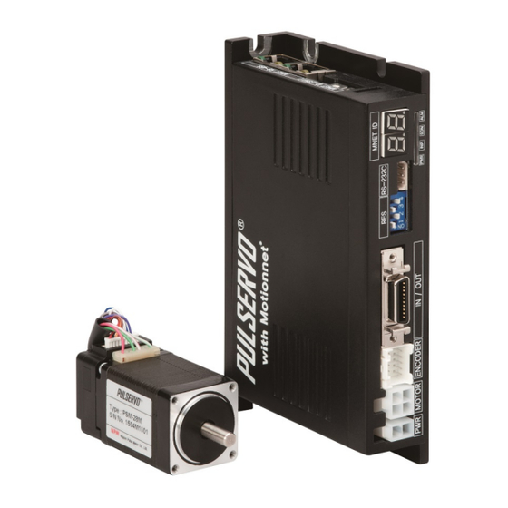
NPM PULSERVO User Manual (127 pages)
Closed-loop stepping motor
Brand:
NPM
| Category:
Control Unit
| Size: 3 MB
Table of Contents
Table of Contents
2
1 Introduction
7
How to Use this Manual
7
Symbol Description
7
Technical Terminology
10
Handling the Product
11
Storing
11
Unpacking
11
Safety
11
Product Warranty
15
Warranty Period
15
Warranty Scope
15
Notice
15
Confirmation
15
2 Pulservo's Features
16
3 Product Model
20
How to See Product Models
20
Pulse Input Type
21
Combination Models of a Standard Motor and a Driver
21
Combination Models of a Motor with Brake and a Driver
21
Combination Models of a Motor with Gearhead and Drivers
22
Motionnet Type
23
Combination Models of a Standard Motor and a Driver
23
Combination Models of a Motor with Brake and a Driver
23
Combination Models of a Motor with Gearhead and a Driver
24
4 Motor Specifications and External Dimensions
25
Motor Specifications and External Dimensions of Standard Type
25
Motor Specifications
25
Torque Characteristic
26
Motor External Dimensions
28
Specifications of Motors with Brakes
38
Motor Specification
38
Motor External Dimensions
39
Specifications and External Dimensions of Motors with Gearheads
45
Motor Size 42 Geared Model Specifications
45
Motoro Size 56 Geared Model Specifications
46
Motor Size 60 Geared Model Specifications
47
Motor External Dimensions
48
Lead Wire
51
5 Cable Specifications
52
Input / Output Signal Cable
52
For Pulse Input Type
52
For Motionnet Type
52
Encoder Junction Cable
52
Motor Junction Cable
53
Power Cable for Driver
53
Parameter Setting Cable
53
Motionnet Dedicated Cables (RJ45 - RJ45 Types)
54
Cable Diagram
55
Motor Junction Cable Diagram
55
Encoder Junction Cable Diagram
55
Parameter Setting Cable Diagram
56
6 Accessories
57
Accessories for Pulse Input Type
57
Accessories for Motionnet Type
57
Accessories for Motors with Brake
57
7 Parameter Setting
58
Parameter Setting Program
58
Parameter Items
59
8 Monitor Feature
61
Equipment Configuration / Connection
61
Monitor Function Specifications
62
Monitor Function Command
62
Example to Use Monitor Functions
66
In Memory Mode
66
In Free-Run Mode
66
Pulse Input Type
67
9 Driver Specifications and External Dimensions
68
Specifications
68
External Dimensions
70
10 System Configuration
71
11 Precautions for Mounting
72
12 External Connection Diagram
73
13 Operation Display and Setting
74
Operation Display LED
74
Resolution Setting Switch (RES1 to 4)
75
Motor Direction Switch (DIR)
75
Pulse Input Method Setting Switch (2P/1P)
75
14 Connector Pin Assignment
76
Power Connector (CN1)
76
Motor Connector (CN2)
76
Encoder Connector (CN3)
76
Input / Output Signal Connector (CN4)
77
Parameter Setting Connector (CN5)
77
15 Input / Output Signals
78
Input Signals
78
CW, CCW Input
78
Alarm Reset, Servo-ON/OFF Input
79
Output Signals
80
Alarm, In-Position Output
80
A, B, Z Encoder Output
81
16 Diagnosis for Failure and Countermeasures
82
When the Alarm LED Is Not Blinking
82
When the Alarm LED Is Blinking
83
Motionnet Type
87
17 Driver Specifications and External Dimensions
88
Specifications
88
Motor Driver Specifications
88
Serial Communication and Motion Control Part Specifications
90
External Dimensions
91
18 System Configuration
92
19 Precautions for Mounting
92
20 External Connection Diagram
93
21 Operation Display and Setting
94
Operation Display LED
94
Motionnet Communication Display LED
95
Resolution Setting Switch (RES1 to 4)
95
Limit Signal Logic Setting Switch (SW1.1)
96
Motionnet Communication Speed / Termination Resistor Switch (SW1.2 to SW1.4)
96
Device Number Setting Switch (SW3, SW4)
97
22 Connector Pin Assignment
98
Power Connector (CN1)
98
Motor Connector (CN2)
98
Encoder Connector (CN3)
98
Input / Output Signal Connector (CN4)
99
Motionnet Connectors (CN5, CN6)
99
Parameter Setting Connector (CN5)
99
23 External Input / Output Signals
100
External Input Signals
100
Limit, Slow-Down, ORG, Simul Start/Stop, In1, In2, Emg.stop and Latch Input
100
External Output Signals
101
Out1/2, Compare, Alarm, In-Position Output
101
Serial Communication (RS485+, RS485−)
102
24 Internal I/O Signals between Motor Driver and G9
103
Output from G9103
103
Motor Drive Command Pulse Output
103
Motor Excitation Output
104
Alarm Reset Output
107
Input to G9103
108
ALM Input
108
INP Input
109
Encoder Input
110
25 G9103 Internal Setting List
111
Environment Setting 1 (RENV1)
111
Environment Setting 2 (RENV2)
111
Assignment of General-Purpose I/O and the Status
112
26 Diagnosis for Failure and Countermeasures
113
When the Alarm LED Is Not Blinking
113
When the Alarm LED Is Blinking
114
Advertisement
Advertisement
Related Products
NPM PCD45oo Series
NPM PCL50oo Series
NPM PCD4500
NPM PCD 4511
NPM PCD 4541
NPM PCL-240AK
NPM PCL-240MS
NPM PCL3013
NPM PCL5022
NPM PCL5023
NPM Categories
Motherboard
Controller
Control Unit
Computer Hardware
Personal Care Products
More NPM Manuals
Login
Sign In
OR
Sign in with Facebook
Sign in with Google
Upload manual
Upload from disk
Upload from URL