Sign In
Upload
Manuals
Brands
North Atlantic Manuals
Laboratory Equipment
SRS 5330A
North Atlantic SRS 5330A Manuals
Manuals and User Guides for North Atlantic SRS 5330A. We have
1
North Atlantic SRS 5330A manual available for free PDF download: Operation Manual
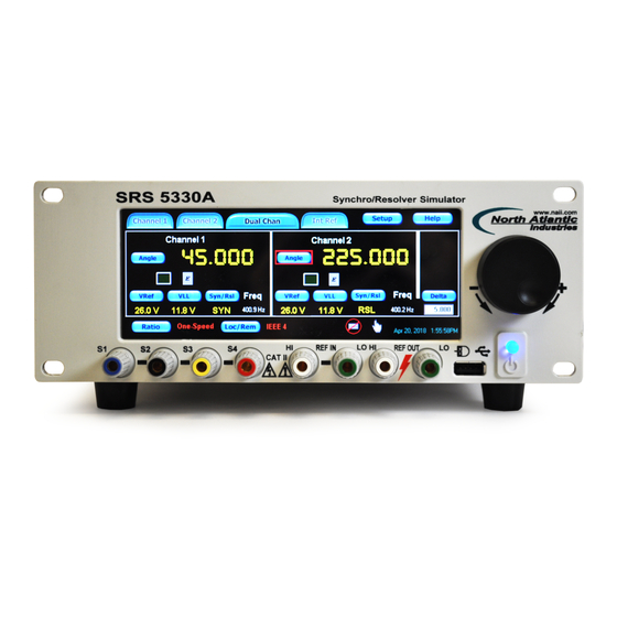
North Atlantic SRS 5330A Operation Manual (24 pages)
SYNCHRO/RESOLVER SIMULATOR
Brand:
North Atlantic
| Category:
Laboratory Equipment
| Size: 1.78 MB
Table of Contents
General
1
Description
1
Features
1
Specifications Synchro or Resolver
2
Reference Generator, (See Part Number)
2
General
2
Table of Contents
3
Table of Figures
4
Safety Summary
5
General Safety Notices
5
Repair
5
High Voltage
5
Input Power Always on
5
Interfaces, Communication
6
J2 Connector, Ieee- 488 Pin Designations
6
J3 Connector
6
USB-A (USB 2.0) Rear Connector, for Communications Only
6
J4 Connector
6
USB-A Front Panel Connector for Optical Mouse Only
6
Controls & Indicators, General Description
7
Figure 1 - Front Panel Controls & Connections
7
Figure 2 - Indicators on the Front Panel Main Display of the 5330A
7
Channel Selection
8
Synchro/Resolver Mode Select
8
Figure 3 - Channel Selection
8
Figure 4 - Synchro / Resolver Mode Select
8
VLL (Voltage Line-To-Line) Output Select
9
Fixed/Ratiometric (Voltage Output Mode Select)
9
Angle Set
9
Phase Offset
9
Figure 5 - VLL Output Select & Fixed/Ratiometric Mode
9
Figure 6 - Angle Set
9
Figure 7 - Phase Offset Control
9
Channel Output, Enable
10
INT/EXT (Reference Source Select)
10
VREF (External Reference Voltage Set)
10
Internal Reference Setup
10
Figure 8 - Output Enable
10
Figure 9 - Internal Reference Setup
10
Remote Sense Setup
11
Over Current
11
Delta Screen Panel
12
Ratio (Multi-Speed) Mode
12
Figure 10 - Delta Screen Panel
12
Figure 11 - Ratio (Multi-Speed) Mode
12
Figure 12 - Ratio Select
12
Dynamic Mode Control Panel
13
Programming
13
Remote Programming / Legacy 5330/5310 Support
13
Compatibility to 5330/5310 Srss
13
Figure 13 - Rotation Mode
13
Figure 14 - Remote Operation
13
Ethernet Port Selection
14
Figure 15 - USB Port Selection
14
Figure 16 - Ethernet Port Selection
14
Figure 17 - IEEE-488 Port Selection
14
USB Port Selection
14
Setup Menus
15
Figure 18 - Setup Menus
15
Figure 19 - Options Menu
15
Figure 20 - Factory Setting
16
Figure 21 - Custom Settings
16
Figure 22 - Brightness Control
16
Figure 23 - Calibration Menu
17
Figure 24 - Help Menus
17
Figure 25 - Default Values
17
Ordering Information
18
Accessories
18
Optional Mounting Accessory
18
Installation and Maintenance
19
Unpacking and Inspection
19
Shipping
19
Installation
19
Rack Mounting Instructions
19
Bench Installation
19
Maintenance
19
Input AC Power Fuse(S)
19
High Voltage Is Used in the Operation of this Equipment
20
Input Power Always on
20
Rear Panel Cooling Fan Filter
20
Calibration
20
Self-Calibration
20
Calibration Verification
20
Figure 26 - Maintenance; Cooling Fan Filter
20
Mechanical Outline, Model 5330A
21
J3 Connector
21
USB-A (USB 2.0) Rear Connector, for Communications Only
21
J4 Connector
21
USB-A Front Panel Connector for Optical Mouse Only
21
Supplemental Information for Units Sold Within the European Union
22
General
22
Specifications
22
Environmental
22
Fuses
22
Line Cord
22
Installation and Mains Input
22
Safety Grounding
22
Improper Usage
22
Technical Assistance
22
5330A Series Declaration of Conformity
23
Revision History
24
Advertisement
Advertisement
Related Products
North Atlantic Categories
Measuring Instruments
Switch
Recording Equipment
Computer Hardware
Media Converter
More North Atlantic Manuals
Login
Sign In
OR
Sign in with Facebook
Sign in with Google
Upload manual
Upload from disk
Upload from URL