Sign In
Upload
Manuals
Brands
Nortel Manuals
Controller
QPC757
Nortel QPC757 Manuals
Manuals and User Guides for Nortel QPC757. We have
1
Nortel QPC757 manual available for free PDF download: Installation Manual
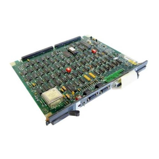
Nortel QPC757 Installation Manual (186 pages)
ISDN Primary Rate Interface
Brand:
Nortel
| Category:
Controller
| Size: 0.52 MB
Table of Contents
Table of Contents
3
List of Tables
11
Table
12
Introduction
14
Document Organization
14
References
16
Note to Installers
17
Primary Rate Interface Equipment: Overview
18
PRI Hardware
20
Minimum ROM Requirements by Machine Type and X11 Release
21
Table 1
21
ISDN Signaling Link Hardware
22
Qpc720 Pri
23
Power Requirements
23
QPC720 Faceplate
24
Cable Requirements
24
QPC720 PRI: External Connectors
24
QPC720 PRI Faceplate Layout
25
Carrier Interface
26
Echo Canceller Interface
26
64 T-Link Version 2 Protocol
27
QPC720 PRI: Cables and Cable Lengths
27
Qpc757 Dchi/Nt6D80 Msdl
28
Power Requirements
28
Interface to PRI
28
QPC757/NT6D80 Faceplate
28
QPC757 DCHI Faceplate Layout
30
Nt6D80 Msdl
31
Power Requirements
31
MSDL/PRI Interface
31
MSDL Faceplate
31
Figure 4
32
NT6D80 MSDL Faceplate Layout
32
Clock Operation
33
Tracking Mode
33
Free Run (Non-Tracking) Mode
33
Holdover Mode
33
Reference Clock Errors
33
Clock Controller Primary and Secondary Tracking
34
Automatic Clock Recovery
35
Automatic Clock Switching
35
DTI to PRI Conversion
36
PRI Circuit Card (QPC720) Option Settings
37
Transmission Equalization Switch Settings for QPC720 PRI/DTI Mode
38
PRI Installation: ST, STE, 21, 21E
39
PRI Circuit Card Locations
39
Cable Requirements
39
Installing the QPC720 PRI
40
Shelf and Slot Location of QPC720 in ST and Option 21
40
Transmission Equalization Switch Settings for PRI
41
Table
41
Table 7
42
Cable Connections and Destinations for ST, STE, 21, 21E
42
Figure 7
43
ST, STE, 21, 21E Cabling Without Echo Canceller
43
Figure 8
44
ST, STE, 21, 21E Cabling with Echo Canceller
44
PRI Card (QPC720) Switch Settings
45
Removing the QPC720 PRI
46
PRI Installation: RT
47
PRI Circuit Card Locations
47
Cable Requirements
47
Installing the QPC720 PRI
48
Shelf and Slot Location of QPC720 in RT
48
Transmission Equalization Switch Settings for PRI
49
Table 10
50
Cable Connections and Destinations for RT
50
Figure 10
51
RT Cabling Without Echo Canceller
51
Figure 11
52
RT Cabling with Echo Canceller
52
PRI Card (QPC720) Switch Settings
53
Removing the QPC720 PRI
54
PRI Installation: NT, 51/51C, 61/61C
55
PRI Circuit Card Locations
55
Cable Requirements
55
Installing the QPC720 PRI
56
Shelf and Slot Location of QPC720 in NT or Option 61
56
Removing the QPC720 PRI
58
Transmission Equalization Switch Settings for PRI
59
Cable Connections and Destinations for NT, 51/51C, 61/61C
60
Half Group Cabling Without Echo Canceller
61
Half Group Cabling with Echo Canceller
62
Single Group Cabling Without Echo Canceller (NT, 61/61C)
63
Single Group Cabling with Echo Canceller (NT, 61/61C)
64
PRI Card (QPC720) Switch Settings
65
PRI Installation: XT, 71
66
PRI Circuit Card Locations
66
Cable Requirements
66
Installing the QPC720 PRI
66
Figure 20
67
Table 14
67
Table
68
Figure 18
69
XT, 71 Cabling Without Echo Canceller
69
XT, 71 Cabling with Echo Canceller
70
Option Switch Settings for PRI Circuit Card
71
Table 15
72
Transmission Equalization Switch Settings for PRI
72
Table 16
73
Table 16
74
Removing the QPC720 PRI
75
Cable Connections and Destinations for XT, 71
74
PRI Installation: 81/ 81C
76
PRI Circuit Card Locations
76
Cable Requirements
76
Installing the QPC720 PRI
76
Shelf and Slot Location of QPC720 in 81
77
Table 17
77
Figure 21
78
Option 81/81C Cabling Without Echo Canceller
78
81/81C Cabling with Echo Canceller
79
Option Switch Settings for PRI Circuit Card
80
Table 18
81
Transmission Equalization Switch Settings for PRI
81
Table 19
82
Table 19
83
Removing the QPC720 PRI
84
Cable Connections and Destinations for 81/81C
83
Clock Controller Installation
85
Determining Slots and Shelves
86
Clock Controller Shelves and Slots
86
Clock Controller Switch Settings for QPC471 Vintage a
86
Table 20
86
Clock Controller Switch Settings for QPC471 Vintages B through G
87
Table 22
87
Clock Controller Switch Settings for QPC471 Vintage H
88
Clock Controller Switch Settings for QPC775
88
Table 23
88
Replacing a Clock Controller
89
Installing a Clock Controller
89
Starting the Clock Controller
89
Clock Controller Commands
89
Installing the Clock Controller in a Single Group
92
DCHI Installation for All Systems
96
Installing the QPC757 DCHI
96
QPC757 Option and PRI/ISL High Speed Programming Switch Settings
98
Figure 25
99
QPC757 Option Switch Settings for PRI/ISL Low Speed Programming
99
D-Channel Parameter Downloading
100
Removing the QPC757 DCHI
101
MSDL Installation for All Systems
102
Installing the MSDL
102
Figure 26 MSDL Card Layout
104
MSDL Switch Settings
105
NTD12 Dual-Port DTI/PRI Card Description and Installation
107
NT5D12 Dual-Port DTI/PRI (DDP) Card Overview
107
Supported Software Releases
108
Table 26
108
NTBK51AA Daughterboard
109
D-Channel and MSDL Interface
110
DDP Faceplate
112
Figure 27 - NT5D12 Faceplate - General View
113
Figure 28 - DDP Faceplate - Detailed View
114
System Capacity and Performance
118
Physical Capacity
118
D-Channel Capacity
118
CPU Capacity
118
Power Requirements
119
Testability and Diagnostics
120
Hardware Required for DDP Configuration
121
Cabling Requirements
123
Trunk Tip/Ring Cables
124
Table
125
Table
127
Reference Clock Cables
129
MSDL/DCHI Cables
130
Cabling Diagrams
132
Figure 29 - DDP Cabling for Meridian 1 and Meridian SL-1 Systems with an
133
Clocking
135
Clock Operation
135
Reference Clock Errors
137
Automatic Clock Recovery
137
Automatic Clock Switching
138
Clocking Configurations
138
Table
139
Figure
141
Figure
142
Figure
143
Figure
144
DDP Installation and Removal
145
DDP Circuit Card Locations
145
Port Definitions
145
Replacement of a Digital Trunk (QPC720/QPC472) by a DDP Card
146
DDP Switch Settings
147
General Purpose Switches
147
Trunk Interface Switches
148
Ring Ground Switches
149
DCH Mode and Address Select Switches
150
Installing the NT5D12 DDP
154
Removing the NT5D12 DDP
156
Configuring the NT5D12 DDP
157
DDCH Installation for All Systems
158
Installing the DDCH Daughterboard
159
DDCH Removal for All Systems
160
Removing the DDCH Daughterboard
160
Echo Canceller for All Systems
161
PRI to Echo Canceller Pin Assignments
161
Table 41
161
Electromagnetic Interference
162
Echo Canceller Initialization Procedures
162
Echo Canceller Operating Parameters
162
Table 42
162
ISL Installation for All Systems
164
ISL Configurations
164
DCHI Switch Settings
164
MSDL Switch Settings
166
Figure
166
Shared Mode
167
Dedicated Mode Using Leased Line
168
Dedicated Mode Using Dial-Up Modem
168
Figure 43
169
Pin Assignment for D-Channel RS-232 Interface
170
Table 44
170
Dedicated Mode Using PRI/DTI Trunks
171
ISL Installation
173
ISL Dedicated Mode (Digital and Analog)
174
ISL Shared Mode
174
PRI Cabling Information
175
Qcad128/Nt8D83Xx
175
Qcad128/Nt8D83Xx Wire List
176
Table 45
176
Qcad129/Nt9J93Xx
177
Qcad129/Nt9J93Xx Wire List
177
Table 46
177
Qcad133/Nt8D83Xx
178
Qcad133/Nt8D83Xx Wire List
178
Table 47
178
Qcad328
179
QCAD328 Wire List
179
Table 48
179
NT8D74 Clock Controller to Intergroup Cable
180
NT8D75 Clock Controller to Clock Controller Cable
180
NT8D79 PRI/DTI to Clock Controller Cable
180
NT8D83 PRI/DTI to I/O Cable
181
NT8D85 Network to PE Cable
181
NT8D86 Network to I/O Cable
182
NT8D97AX PRI/DTI I/O to MDF Cable
182
NT9J93AD PRI/DTI Echo Canceller to I/O Cable
182
NTND26 PRI to MSDL Cables
182
NTND27 MSDL to I/O Panel Cables
183
NTND98 PRI to I/O Panel Cables
183
Card Slot Positions for 21/ 21E, 51/51C, 61/61C, 71, and 81/81C
184
Table 49
184
Table 50
185
Card Slot Positions for ST, STE, RT, NT, XT
185
Advertisement
Advertisement
Related Products
Nortel QPC720
Nortel QPC471
Nortel QPC775
Nortel QPC192
Nortel QPC452
Nortel QPC578
Nortel QPC789
Nortel QPC472
Nortel QPC705
Nortel QPC706
Nortel Categories
IP Phone
Telephone
Switch
Software
Server
More Nortel Manuals
Login
Sign In
OR
Sign in with Facebook
Sign in with Google
Upload manual
Upload from disk
Upload from URL