Sign In
Upload
Manuals
Brands
Nidek Manuals
Measuring Instruments
AR-660A
Nidek AR-660A Manuals
Manuals and User Guides for Nidek AR-660A. We have
1
Nidek AR-660A manual available for free PDF download: Service Manual
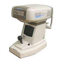
Nidek Medical AR-660A Service Manual (165 pages)
Brand:
Nidek Medical
| Category:
Measuring Instruments
| Size: 2.29 MB
Table of Contents
Table of Contents
3
1 Introduction
8
3 Troubleshooting
9
The TV Monitor Display Nothing/The Monitor Display Is Abnormal
15
The Message "Err" Appears after Turning on the Power Switch
16
Err 1" (Sensor Carry Error) Appears
16
Err2" (Chart Carry Error) Appears
17
Err 3" (Rotary Error) Appears
18
Err 4" (Chart Error) Appears
19
Err 5"(CL1 Error) or "Err 6" (CL2 Error) Appears
19
Err 7"([Line] Printer Error) Appears
20
Err 8"([Serial] Printer Error)Appears
20
Err 9" (MEMORY FAILURE on E2PROM) Appears
21
Err A" (MEMORY FAILURE on RAM) Appears
21
PD ERR" Appears
22
The Shutter Does Not Open (Only for AR-600 Whose S/N Is Earlier than 10121)
23
The Raster Does Not Appear (the TV Monitor Does Not Light Well)
23
Eye Image Does Not Appear on the TV Monitor
23
The Characters or Target Are Not Clear or They Do Not Appear on the TV Monitor
24
The Switching between the Manual Mode and Auto-Tracking Mode Can Not be Done
24
The Instrument Can Not be Placed into the Mode Where the Objective Measurement Is Performed
24
The Parameter Settings Can Not be Changed
25
The Measuring Mode Can Not be Changed
26
The Movement of the Measuring Unit Is Not Smooth on a Plane
26
The Vertical Movement of the Measuring Unit Is Not Smooth
26
The Measuring Unit Is Unstable
27
The Alignment Light Does Not Appear (Only for AR-600 Series)
27
The Mire Ring Does Not Appear (Only for ARK-700 Series)
27
The Model Eye Image Is Not Clear
28
AR Measurement Does Not Start
28
The Message "Err" Appears During AR Measurements
29
Only the Obtained SPH Value Is Shifted
30
A Short Beep Can Not be Heard When Pressing the Start Button
32
The IOL Mode Can Not be Turned on
32
The Cylinder Mode Can Not be Changed
32
The Instrument Can Not Recognize the Left and Right
33
The Instrument Can Not be Placed in the PD Mode
33
The Obtained PD Value Is Abnormal
34
The Message "Err" Appears During KM Measurement
34
The Obtained KM Value Is Abnormal
34
The Up-And-Down Movement of the Chin Rest Is Not Smooth
35
The Charts Can Not be Seen
35
Err" Does Not Appear Though the Patient Blinked During Measurement
36
The Auto-Tracking Function Does Not Work
37
The Auto-Shot Function Does Not Work
38
The Instrument Can Not be Placed in the VA TEST Mode
38
VA Charts Can Not be Changed
39
The Presented Chart Is out of Focus During the Subjective Measurement (Except When a Patient Has Irregular Astigmatism)
39
The Message "Err IF" (Interface Error) Appears
40
The Printer Does Not Operate
41
Light Printed Text/Loss of Text
41
The Eyeprint Function Can Not be Turned on
42
The TV Auto-OFF Function Does Not Work
42
The Shutter Does Not Close (Only for the Instruments Whose S/N Earlier than 10121)
42
4 Checking the Obtained Data with Model Eyes
43
Cleaning the Model Eyes and Steel Balls
43
Cleaning the Measuring Window
44
Measuring the Model Eyes
45
Tolerance on AR Measurement Error
45
Measuring the Steel Balls
46
Tolerance on KM Measurement Error
46
5 Removing Covers
47
Removing the Front, Left and Right Covers
47
Removing the Rear Cover of the Measuring Unit
49
Removing the Inner Cover
49
Removing the Rear Cover
50
Removing the TV Panel
51
Removing the Bottom Plate of the Instrument
52
6 Checking the Mains Supply Condition
53
Checking the Supply Voltage to AC INLET
53
Checking the Secondary Voltage of the Transformer
53
Checking Output Voltage on PC7 Board
54
Checking Output Voltage from Backup Battery
54
Checking Voltage in D1 and D2 on the PC6 Board
55
7 Checking Continuity of Switches
56
Start Sw
56
Switches on the PC2 Board
56
Switches on the PC3 Board (Except AR-600)
58
Switches on the PC12 Board (Only for AR-660A and ARK-760A)
59
8 Checking Electric Parts
60
Checking Origin Sensor for the Chart Carry
60
Checking L/R Origin Sensor (Except AR-600 & ARK-700)
61
Checking the Origin Sensor for the Rotator
62
AR Measurement LED and LED Cable
63
Checking the ILLUMI. LED Voltage
64
Checking the Chart Lamp Voltage
64
Checking the Alignment Light LED Voltage
64
Checking the PD LED Voltage
64
Checking the FOCUS LED Voltage (Only for AR-600A, AR-660A)
65
Checking the AKM LED Voltage (Only for AR-700 Series)
65
Checking the AKM LED Voltage (Except AR-600)
65
9 Replacing Circuit Boards
66
Replacing PC1 (MAIN) Board
66
Replacing PC2 (DISPLAY) Board
67
Replacing PC3 (INC.DEC SW) Board (Except AR-600)
68
Replacing PC6 (ADJUST) Board
69
Replacing PC7 (POWER SUPPLY) Board
70
Replacing PC8 (PRINTER) Board and Printer
71
Replacing PC10 (MIRE) Board
73
Replacing PC12 (CHART SELECT SW) Board
75
Replacing the PC22 (TRACKING) Board
76
Replacing the PC23 (PD CCD) Board
77
Replacing the PC24 (PD LED) Board
78
10 Replacing Parts
79
Replacing the Transformer
79
Replacing the Joystick
80
Cleaning and Replacing the Slide Plate
81
Replacing LED and Cleaning IR Filter
82
Replacing LED and Cleaning of the G29
83
Replacing the
84
Replacing the FOCUS LED
85
Replacing the Shutter
86
Replacing the LED Cable
87
Replacing the Chart Lamp
88
Replacing the Rotator Unit Origin Sensor
90
Replacing U/D Limit Switches
91
Replacing the Left and Right Limit Sensor Unit
93
Replacing the U/D Motor
94
Replacing the R/L Motor (for Moving the Instrument to the Right or Left) (Except AR-600 and ARK-700)
95
Replacing the TV Monitor
96
Replacing the CCD Camera
97
Replacing the Chart Unit
98
Replacing CYL Unit (Only for AR-660A and ARK-760A)
99
Replacing the Battery
100
Replacing the Measuring Unit
101
11 Adjusting each Part
103
Adjusting the Sway Stopper Unit
105
Adjusting the Up-And-Down Movement of the Chin Rest
106
Calibrating by Adjusting the Focus of CCD Camera Lens
108
Positioning the Target Square
109
Sensor Calibration (Adjusting VR1 and VR2 on the PC6 Board)
110
KM Auto-Calibration (Only for ARK-700 Series)
112
Setting EEPROM DATA
114
Setting Sensor Offset (SO)
115
Setting Print Density (PC)
116
Setting Target Offset (TO)
117
Setting Target Gain (TG)
117
Setting PD Gain (PA)
118
Setting Mask Blink Level (ML)
118
Setting Horizontal Position (HP) of Display
119
Setting Vertical Position (VP) of Display
119
Adjusting Scale for CS (Corneal Size) Measurement (Only for ARK-700 Series)
120
Setting CYL Zero (C1) and CYL Axis (C2)
122
(Only for AR-660A and ARK-760)
122
Adjusting Image Centering
123
Adjusting Brightness and Sharpness of Display
124
Tracking Auto-Calibration (Except AR-600 and ARK-700)
125
12 Program for Adjustment
128
13 Replacing ROM (Program)
130
14 List of SW1 and SW2 Operations
131
15 Principle of Measurement
133
16 References
137
Construction Drawing
137
Ar-660A Construction Drawing
143
Advertisement
Advertisement
Related Products
Nidek AR-600A
Nidek Medical ARK-1S
Nidek Medical ARK-710A
Nidek Medical ARK-600 Series
Nidek ARK-700
Nidek ARK-700A
Nidek ARK-760A
Nidek Medical AR-600
Nidek Medical ARK-700 Series
Nidek Medical AR-360A
Nidek Categories
Medical Equipment
Measuring Instruments
Edger
Oxygen Equipment
Projector
More Nidek Manuals
Login
Sign In
OR
Sign in with Facebook
Sign in with Google
Upload manual
Upload from disk
Upload from URL