Sign In
Upload
Manuals
Brands
NI Manuals
I/O Systems
SCXI-1120/D
NI SCXI-1120/D Manuals
Manuals and User Guides for NI SCXI-1120/D. We have
1
NI SCXI-1120/D manual available for free PDF download: User Manual
NI SCXI-1120/D User Manual (73 pages)
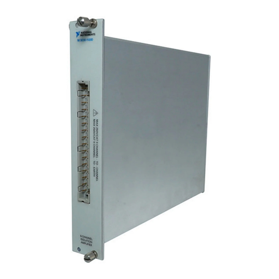
SCXI Eight-Channel Isolated Analog Input Module and Eight-Channel Wide Band Isolated Analog Input Module for Signal Conditioning
Brand:
NI
| Category:
I/O Systems
| Size: 0 MB
Table of Contents
Table of Contents
4
About this Manual
7
Conventions
7
National Instruments Documentation
8
Chapter 1 Introduction
9
About the SCXI-1120/D
9
What You Need to Get Started
10
Unpacking
11
Software Programming Choices
11
National Instruments Application Software
11
NI-DAQ Driver Software
12
Optional Equipment
13
Figure 1-1. the Relationship between the Programming Environment
13
Chapter 2 Configuration and Installation
14
Module Configuration
14
Figure 2-1. SCXI-1120/D Parts Locator Diagram
15
Digital Signal Connections
17
Figure 2-2. Removing the SCXI Module Cover
17
Using Jumpers W42 and W43
18
Using Jumper W44 on Revision C of the SCXI-1120 and All Revisions of the SCXI-1120D
19
Using Jumper W44 on Revisions a and B of the SCXI-1120
19
Table 2-1. Digital Signal Connections, Jumper Settings
20
Analog Configuration
21
Grounding, Shielding, and Reference-Mode Selection
21
Table 2-2. Jumper W46 Settings
22
Direct Temperature Connection
23
Gain Jumpers for the SCXI-1120/D
23
Table 2-3. Jumper W41 Settings
23
Table 2-4. Gain Jumper Allocation
23
Table 2-5. Gain Jumper Positions
24
SCXI-1120 Filter Jumpers
25
Table 2-6. SCXI-1120 Filter Jumper Allocation
25
SCXI-1120D Filter Jumpers
26
Table 2-7. SCXI-1120D Filter Jumper Allocation
26
Hardware Installation
27
Chapter 3 Signal Connections
28
SCXI-1120/D Front Connector
30
Figure 3-1. SCXI-1120/D Front Connector Pin Assignments
30
Front Connector Signal Descriptions
31
Table 3-1. SCXI-1120/D Front Connector Signal Descriptions
31
Analog Input Channels
32
Figure 3-2. Ground-Referenced Signal Connection for the SCXI-1120/D with High Common-Mode Voltage
32
Figure 3-3. Floating Signal Connection for the SCXI-1120/D Referenced to
32
Figure 3-4. Floating AC-Coupled Signal Connection for the SCXI-1120
33
High Common-Mode Voltage
33
Temperature Sensor Connection
34
High Common Mode Voltage
34
Floating AC-Coupled Signal Connection for the SCXI-1120D
34
SCXI-1120/D Rear Connector
35
SCXI-1120/D Rear Signal Connector Pin Assignments
35
Rear Connector Signal Descriptions
36
Table 3-2. Rear Connector Signal Descriptions
36
Analog Output Signal Connections
37
Table 3-3. Scxibus to SCXI-1120/D Rear Connector to DAQ Device Pin Equivalencies
38
Chapter 4 Theory of Operation
39
Functional Overview
39
Power-Up State
40
Scxibus Connector and Digital Interface
41
Digital Interface Circuitry Block Diagram
41
Digital Control Circuitry
42
Analog and Timing Circuitry
43
Analog Input Channels
44
Analog Input Block Diagram
44
Analog Output Circuitry
47
Chapter 5 Calibration
50
Calibration Equipment Requirements
50
Offset Null Adjust
50
Table 5-1. Calibration Potentiometers Reference Designators
51
Appendix A Specifications
52
Table A-1. Input Signal Range
56
Table A-2. System Noise RTI (0.1 Hz to 50 Khz
57
Table A-3. Switching Supply Noise (Approximately at 100 Khz
58
Appendix B Technical Support Resources
60
Mexico (Monterrey) 8 357 7695, Netherlands 0348 433466, Norway 32 27 73 00, Singapore
61
Advertisement
Advertisement
Related Products
NI SLSC-12202
NI SMA-2164
NI SCB-8
NI SMB-2163
NI SCXI-1127
NI SCXI-1333
NI SCXI -1334
NI SCXI-MS100
NI SCXI-1379
NI SCC-LP02
NI Categories
Control Unit
I/O Systems
Controller
Measuring Instruments
Chassis
More NI Manuals
Login
Sign In
OR
Sign in with Facebook
Sign in with Google
Upload manual
Upload from disk
Upload from URL