Sign In
Upload
Manuals
Brands
NI Manuals
Control Unit
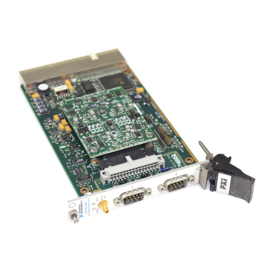
PXI-4220
NI PXI-4220 Manuals
Manuals and User Guides for NI PXI-4220. We have
1
NI PXI-4220 manual available for free PDF download: User Manual
NI PXI-4220 User Manual (125 pages)
Brand:
NI
| Category:
Control Unit
| Size: 3 MB
Table of Contents
Table of Contents
6
About the ni PXI-4220
11
What You Need to Get Started
12
Installing the Application Software, NI-DAQ, and the DAQ Device
13
National Instruments Documentation
13
Installing the ni PXI-4220
14
LED Pattern Descriptions
14
Connecting Bridge Sensor Signals to the ni PXI-4220
15
Connecting Signals
15
Figure 2-1. ni PXI-4220 Front Label
16
Figure 2-2. PXI-4220 Front Connector and General Circuit Diagram
17
Figure 2-3. Socketed Resistor Locations
18
Quarter-Bridge Type I
18
Figure 2-4. Quarter-Bridge I Circuit Diagram
19
Figure 2-5. Quarter-Bridge II Circuit Diagram
20
Quarter-Bridge Type II
20
Figure 2-6. Half-Bridge Type I Circuit Diagram
21
Half-Bridge Type I
21
Figure 2-7. Half-Bridge Type II Circuit Diagram
22
Half-Bridge Type II
22
Figure 2-8. Full-Bridge Type I Circuit Diagram
23
Full-Bridge Type I
23
Figure 2-9. Full-Bridge Type II Circuit Diagram
24
Full-Bridge Type II
24
Figure 2-10. Full-Bridge Type III Circuit Diagram
25
Full-Bridge Type III
25
Figure 2-11. Remote Sense Circuit Diagram
26
Remote Sense
26
Configuring and Testing
27
Verifying and Self-Testing Using Device Test Panels
27
Bridge Configuration and Completion
28
Common Software-Configurable Settings
28
Excitation Level
28
NI PXI-4220 Software-Configurable Settings
28
Filter
29
Gain/Input Range
29
Offset Null Compensation Potentiometers
29
Table 3-1. Excitation Voltage for Configuration and Gauge Resistances
29
Configurable Settings in MAX
30
Shunt Calibration Switches
30
Simultaneous Sample and Hold
30
NI-Daqmx
31
Creating a Strain Global Channel or Task
32
Creating a Custom Voltage with Excitation Global Channel or Task
33
Verifying the Signal
34
Verifying the Signal in NI-Daqmx Using a Task or Global Channel
34
Figure 4-1. Basic Wheatstone Bridge Circuit Diagram
36
Strain Gauge Theory
36
Theory of Operation
36
Wheatstone Bridges
36
Acronyms, Formulas, and Variable Definitions
37
Strain Gauges
37
Table 4-1. Strain-Gauge Configurations
37
Software Scaling and Equations
38
Figure 4-2. Quarter-Bridge Type I Measuring Axial and Bending Strain
39
Figure 4-3. Quarter-Bridge Type I Circuit Diagram
39
Quarter-Bridge Type I
39
Figure 4-4. Quarter-Bridge Type II Measuring Axial and Bending Strain
41
Quarter-Bridge Type II
41
Figure 4-5. Quarter-Bridge Type II Circuit Diagram
42
Figure 4-6. Half-Bridge Type I Measuring Axial and Bending Strain
43
Half-Bridge Type I
43
Figure 4-7. Half-Bridge Type I Circuit Diagram
44
Figure 4-8. Half-Bridge Type II Rejecting Axial and Measuring Bending Strain
45
Half-Bridge Type II
45
Figure 4-9. Half-Bridge Type II Circuit Diagram
46
Figure 4-10. Full-Bridge Type I Rejecting Axial and Measuring Bending Strain
47
Full-Bridge Type I
47
Figure 4-11. Full-Bridge Type I Circuit Diagram
48
Figure 4-12. Full-Bridge Type II Rejecting Axial and Measuring Bending Strain
49
Full-Bridge Type II
49
Full-Bridge Type III
51
Figure 4-14. Full-Bridge Type III Measuring Axial and Rejecting Bending Strain
52
Figure 4-15. Full-Bridge Type III Circuit Diagram
52
NI PXI-4220 Theory of Operation
53
Figure 4-16. Block Diagram of the ni PXI-4220
54
Bridge Configuration and Completion
56
Excitation
56
Remote Sense
57
Gain/Input Range
59
Filter
60
Offset Null Compensation
61
Table 4-2. Control Codes for Coarse and Fine Null Potentiometers
61
Shunt Calibration
62
Simultaneous Sample and Hold
63
Figure 4-17. Signal During Simultaneous Sample and Hold Sampling
64
Common-Mode Rejection Ratio
65
Differential Signals
65
Maximum Acquisition Rate
65
Measurement Considerations
65
Table 4-3. Maximum Sampling Rates
65
Effective CMR
66
Timing and Control Functional Overview
66
Figure 4-18. AI CONV CLK Signal Routing
67
Programmable Function Inputs
67
Device and PXI Clocks
68
Figure 4-19. ni PXI-4220 PXI Trigger Bus Signal Connection
69
Table 4-4. PXI Trigger Bus Timing Signals
70
Developing Your Application
71
Developing Your Application in NI-Daqmx
71
Typical Program Flow
71
Figure 5-1. Typical Program Flowchart
72
Creating a Task Using DAQ Assistant or Programmatically
73
General Discussion of Typical Flow Chart
73
Adjusting Timing and Triggering
74
Configuring Channel Properties
74
Table 5-1. NI-Daqmx Properties
74
Perform Offset Null Compensation
76
Acquiring, Analyzing, and Presenting
77
Perform Shunt Calibration
77
Completing the Application
78
Developing an Application Using Labview
78
Table 5-2. Programming a Task in Labview
78
Using a Daqmx Channel Property Node in Labview
80
Figure 5-2. Labview Channel Property Node with Filtering Enabled at
81
Synchronization and Triggering
82
Synchronizing the ni PXI-4220
82
Figure 5-3. General Synchronizing Flowchart
83
Synchronizing the ni PXI-4220 Using Labview
84
Table 5-3. Synchronizing the ni PXI-4220 Using Labview
84
Other Application Documentation and Material
85
Calibrating the ni PXI-4220
86
Internal Calibration Procedure
86
Calibrating the System
87
External Device Calibration
87
Offset Null Compensation
87
Shunt Calibration
87
Appendix A Specifications
88
Table A-1. Maximum Sampling Rates
88
Advertisement
Advertisement
Related Products
NI PXI-4204
NI PXIe-6674T
NI PXI-6682
NI PXI-6653
NI PXIe-7972R
NI PXIe-1435
NI IMAQ PXI-1409
NI PXIe-8383mc
NI PXIe-5673E
NI FlexRIO PXIe-7976R
NI Categories
Control Unit
I/O Systems
Controller
Measuring Instruments
Chassis
More NI Manuals
Login
Sign In
OR
Sign in with Facebook
Sign in with Google
Upload manual
Upload from disk
Upload from URL