Sign In
Upload
Manuals
Brands
NEXGEN Manuals
Air Conditioner
NR K541 Series
NEXGEN NR K541 Series Manuals
Manuals and User Guides for NEXGEN NR K541 Series. We have
1
NEXGEN NR K541 Series manual available for free PDF download: Installation, Operation & Maintenance Manual
NEXGEN NR K541 Series Installation, Operation & Maintenance Manual (80 pages)
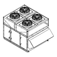
Packaged Compact Rooftop DOAS Unit
Brand:
NEXGEN
| Category:
Air Conditioner
| Size: 2 MB
Table of Contents
Table of Contents
3
Section 1: Safety Introduction and Labeling Guide
5
Warnings, Dangers, Cautions, and Notices
5
Label Placement Guide
6
Figure 1: Label Placement Drawing
6
Figure 2: Sample Unit Data Plate
7
Section 2: Introduction and Pre-Installation
8
Description of Operation
8
Inspection and Setup
8
Unit Nomenclature Example
9
Section 3: Installer Responsibility
12
Introduction
12
Corrosive Chemicals
12
Required Equipment and Materials
12
Section 4: Critical Considerations
13
Required Clearances
13
Service Clearances
14
Ventilation Clearances
14
Unit Placement Considerations
14
Hardware
14
Table 1: Recommended Torque Settings
14
Section 5: National Standards and Applicable Codes
15
Refrigerant Handling Practices
15
Fuel Codes
15
Installation Codes
15
Aircraft Hangers
15
Parking Structures and Repair Garages
15
Electrical
15
Venting
15
High Altitude
15
Section 6: Lifting a Packaged Rooftop Unit
16
SECTION 6: Lifting a Split Air Conditioning Unit 6.1 Moving/Lifting the Unit
16
Figure 3: Lifting a Large Unit (S7 Cabinets)
17
Figure 4: Lifting a Large Unit (S5 Cabinets)
18
Figure 5: Lifting a Large Unit (S3 Cabinets)
19
Section 7: Unit Placement
20
Roof Installation on Curb
20
Roof Curb Assembly and Installation
20
Unit Mounting to Roof Curb
20
Unit Mounting to Ground Pad
20
Figure 6: Roof Curb Installation
20
Section 8: Ductwork Consideration
21
Considerations
21
Inlet Ductwork
21
Return Air Ductwork
21
Discharge Ductwork
21
Section 9: Refrigeration Circuits and Piping
22
Refrigerant
22
Components and Configurations
22
Figure 7: Circuit Diagram for Standard Compressor
23
Section 10: Energy Recovery/Conservation Wheels
24
Principal of Operation
24
Electrical Shock Hazard
24
Routine Maintenance
24
Cleaning the Wheel
25
Section 11: Gas Heater Packages
26
Principle of Operation
26
Gas Piping and Pressure
26
Table 2: Manifold Size and Minimum Pressure
26
Carbon Monoxide Hazard
26
Operating and Safety Controls
27
Wiring
27
Sequence of Operation
27
Figure 8: Example Gas Heater Wiring Diagram - 10.1 Modulation
30
Figure 9: Example Gas Heater Wiring Diagram - Dual Furnace
31
Section 12: Electric Heater Packages
32
Principle of Operation
32
Operating and Safety Controls
32
Wiring
32
Fire Hazard
32
Burn Hazard
32
Table 3: Standard Electric Heaters
33
Figure 10: Example Electrical Heater Wiring Diagram
34
Section 13: Unit Electrical
35
Wiring and Electrical Connections
35
Disconnect
35
Current Draw
35
Wiring Connections
35
Voltage Unbalance
35
Low Voltage Wiring
35
Table 4: Low Voltage Wiring Lengths
35
Figure 11: Example Electrical Wiring Diagram
36
Operation
43
Figure 12: Phase Monitor Data
44
Section 14: Sequence of Operation
45
Unit Configuration
45
Controls Options
45
Figure 13: Equipment Touch Display
45
Basic Sequence of Operation
46
Accessory Controls Options
46
Section 15: Start-Up Procedure
47
Tools & Supplies Required
47
Figure 14: P-Trap Configuration
48
Pre-Start Checks
48
Condensate Drain
48
Table 5: Condensate Connection Sizes
48
Table 6: Hot Water Heating Coil Flow Rate
49
Table 7: Superheat and Subcooling - 100% OA
49
Table 8: Superheat and Subcooling - Recirc
49
Table 9: Superheat and Subcooling - Heat Pump
49
Table 10: Refrigerant Temperature-Pressure
50
Pre-Start Checklist
51
Explosion Hazard
54
Start-Up Form
55
General Information
56
Application Information
56
Unit Information
57
Start-Up Check
58
Energy Conservation
60
SECTION 17: Unit Maintenance
62
Installation Code and Quarterly Inspections
62
General
63
Unit Exterior
63
Direct-Drive Supply and Exhaust Fans
63
Condensing Fans
63
Refrigeration Circuit Components
63
Condensate Drain Pan and Drain
63
Dampers
63
Electric Heater Wiring and Wiring Conn
63
Filters
63
Table 11: Maintenance Guidelines
63
SECTION 18: Replacement Parts
64
Table 12: Air Filters
65
SECTION 19: Troubleshooting
66
Supply Fan
67
Table 13.1: Supply Fan
67
Compressor
68
Table 13.2: Compressor
68
Refrigeration Circuit
70
Table 13.3: Refrigeration Circuit
70
Variable Speed Head Pressure Control
72
Table 13.4: Variable Speed Heat Pressure Control
72
Gas Furnace
74
Table 13.5: Gas Furnace
74
Electric Heater
75
Table 13.6: Electric Heater
75
SECTION 20: Warranty
76
Revision Guide
79
Advertisement
Advertisement
Related Products
NEXGEN NR K540 Series
NEXGEN NR K120 Series
NEXGEN NR K150 Series
NEXGEN NR K210 Series
NEXGEN NR K240 Series
NEXGEN NR K720 Series
NEXGEN NR K09T Series
NEXGEN NR K960 Series
NEXGEN NR K840 Series
NEXGEN NR K660 Series
NEXGEN Categories
Heating System
Control Unit
Thermostat
Air Conditioner
Heater
More NEXGEN Manuals
Login
Sign In
OR
Sign in with Facebook
Sign in with Google
Upload manual
Upload from disk
Upload from URL