Sign In
Upload
Manuals
Brands
Newport Electronics Manuals
Relays
P6000A
Newport Electronics P6000A Manuals
Manuals and User Guides for Newport Electronics P6000A. We have
1
Newport Electronics P6000A manual available for free PDF download: Output Options
Newport Electronics P6000A Output Options (32 pages)
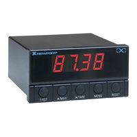
ISOLATED PARALLEL BCD DUAL 8 A RELAY ISOLATED ANALOG OUTPUT
Brand:
Newport Electronics
| Category:
Relays
| Size: 0 MB
Table of Contents
Table of Contents
3
Isolated Parallel Bcd Option Page
7
Electrical Connections
7
Power
7
BCD Outputs
8
Polarity Output
10
Decimal Point Binary Address
10
Overflow Output
10
Alarm Outputs
11
DATA READY Output
11
Instrument Select Inputs
11
HOLD Input
11
General Information
7
Mechanical Installation
7
Jumper Selection
12
Controller Interconnections
13
Figure 5-1 Connections with a Parallel BCD Printer Using Right-Hand Decimal Point
13
Interconnections with a Parallel BCD Printer
13
Figure 5-2 Connections with a Parallel BCD Printer Using Left-Hand Decimal Point
14
Figure 6-1 Parallel BCD Board Assembly Diagram
16
Parallel Bcd Drawings
16
Interface with Programmable Controllers
15
Figure 6-2 Parallel BCD Board Schematic Diagram
17
Dual 8 a Relay Option
18
Electrical Connections and Jumper Selection
18
Figure 3-1 TB4 Connector with Electrical Connections
18
Relay Outputs
18
Figure 3-2 Relay Board Pin Groups
19
Figure 4-1 Relay Board Assembly Diagram
20
Relay Board Drawings
20
Figure 4-2 Relay Board Schematic Diagram
21
Environment
22
General Information
22
Output Control
22
Power and Signals
22
Specifications
22
Configuration Procedure
23
Electrical Connections & Adjustment Locations
23
Figure 3-1 Isolated Analog Output Option Rear View
23
Display Range Selection
24
Output Range Selection
24
Span Range Selection
24
Offset Range Selection
25
Front Panel Setup
26
Mechanical Installation
26
Calibration
27
Current Output (I01, I02)
27
Voltage Output (V01)
27
Current Output (I02)
28
Preamp Zero Adjust (R7)
29
Figure 8-1 Isolated Analog Output Assembly Diagram
30
Isolated Analog Output Drawings
30
S3 of the Relay Board
19
General Information
18
Mechanical Installation
18
Figure 8-2 Isolated Analog Output Schematic Diagram
31
Advertisement
Advertisement
Related Products
Newport Electronics P5000
Newport Electronics Categories
Measuring Instruments
Controller
Thermometer
Monitor
Amplifier
More Newport Electronics Manuals
Login
Sign In
OR
Sign in with Facebook
Sign in with Google
Upload manual
Upload from disk
Upload from URL