Sign In
Upload
Manuals
Brands
Newport Manuals
Measuring Instruments
2835-C
Newport 2835-C Manuals
Manuals and User Guides for Newport 2835-C. We have
1
Newport 2835-C manual available for free PDF download: Manual
Newport
2835-C
Manual
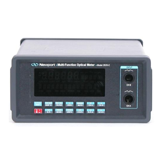
Newport 2835-C Manual (131 pages)
Multi-Function Optical Meter
Brand:
Newport
| Category:
Measuring Instruments
| Size: 1 MB
Table of Contents
Warranty
4
EC Declaration of Conformity
5
Table of Contents
6
List of Figures
9
Safety Symbols and Terms
11
Definitions
12
Specifications
13
Detector Signals and Calculations
16
Section 1 - General Information
17
System Overview
17
Model 2835-C Controller and Accessories
17
Scope of this Manual
18
Unpacking and Inspection
18
Preparation for Use
19
Optional Accessories and Services
19
Section 2 - System Operation
20
Introduction
20
Display
20
Top Level Key Functions
21
Table 1. Model 2835-C Display Annunciators
21
Front Panel Key Pad
22
Table 2. Model 2835-C Top Level Key Functions and Associated Remote Commands
22
DISP , Display Brightness
23
FILTER, Signal Filtering
23
Power
23
Shift
23
AUTO, Automatic Gain Ranging
24
CH a (B), Display Channel a (or B)
24
STO REF, Store Reference Value
24
ZERO, Offset Subtraction
24
RANGE, Signal Range
25
REF SEL, Reference Select
25
Λ, Wavelength
25
MODE, Measurement Mode
26
R/S, Run-Stop
26
Table 3. Newport Detector Families and Available Measurement Modes
26
Table 4. Model 2835-C Measurement Modes
27
UNITS, Display Units
27
R/S a(B), Run-Stop Channel a (or B)
28
STATS, Moving Statistics
28
Table 5. Valid Display Units Available to Detector Families by MODE
28
Table 6. Displayed Unit Abbreviations Vs. Actual Measurement Units
28
Enter
29
ESC, Escape
29
EXT, External Trigger
29
Menu
29
Adjust
30
Menu Level Functions
30
Menu Access and Movement
30
Decimal Point Indication of Menu Hierarchy Position
30
Table 7. Menu Level Key Functions and Parameters
31
Data Store
32
Table 8. Data Store Operations
32
Meter Configuration
33
Table 9. Configuration Parameters and Default Conditions
33
Auto Cal
34
Table 10. Meter Configuration Operations
34
Attenuator
35
Table 11. User Calibration Operations
35
User Calibration
35
DC Sampling
36
Table 12. SAMPLE PREC States and Limits
36
Table 13. DC SAMPLING Operations
36
Trigger Output
36
Table 14. TRIGGER out Operations
37
Table 15. EXT TRIGGER in Operations
37
Trigger Input
37
Bar Graph
38
Detector Switch Position
38
Remote Setup
38
Table 16. BARGRAPH Operations
38
Table 17. TONE Operations
38
Table 18. DET SWITCH POS Operations
38
Table 19. REMOTE SETUP Operations
38
Tone
38
General Information Functions
39
Connecting AC Power
39
Table 20. GENERAL INFO Operations
39
Table 21. Power Supply Voltage Switch Positions
39
Detector Connection and Setup
40
Connecting a Detector with Its Calibration Module
40
Model 2835-C Detector Calibration Module Input Port
40
Power up
41
Performing Basic Measurements
41
Making DC Power Measurements
41
Making Peak-To-Peak Power Measurements
41
Making Pulse Energy Measurements
42
Making a Signal Integration Measurement
42
Measuring a Laser Pulse Energy with a Thermopile Detector
42
Using the Model 2835-C as an Exposure Controller
43
Measuring Laser Pulse Energy Via a Thermopile in INTG Mode
43
Section 3 - Principles of Operation
45
Introduction
45
Analog Signal Flow
45
Model 2835-C Analog Signal Flow Diagram
45
Digitized Signal Flow
46
Model 2835-C Digitized Signal Flow Block Diagram
46
Table 22. Analog Signal Flow Paths
46
Typical Detector Signals
47
Pulse Energy Detector Signals
48
Thermopile Detector Signals
48
Thermopile Signals
48
Peak-To-Peak (Photodiode) Detector Signals
49
Integration of Detector Signals
50
Time Varying Signal Measurements
50
Analog Output
51
Integrated Energy Via a Trapezoid Approximation
51
Measuring Laser Pulse Energy with a Thermopile
51
Measurement Considerations
52
Detector Calibration and Accuracy
52
Quantum Detector Temperature Effects
52
Thermopile Detector Temperature Effects
53
Energy Detector Temperature Effects
53
Ambient and Stray Light
53
Common Measurement Errors
54
Table 23 Common Measurement Errors
54
Section 4 - Computer Interfacing
55
General Guidelines
55
Computer Interface Terminology
55
Entering Remote Computer Interface Mode
57
RS-232C Communication
57
Setting Baud Rate and Echo Mode from the Keypad
58
Setting Baud Rate and Echo Mode from a Remote Interface
58
RS-232C XON/XOFF Handshaking Protocol
59
GPIB Communication
59
Setting the GPIB Address
59
Table 24 Model 2835-C IEEE-488.1 Capabilities Summary
59
Section 5 - Remote Command Reference
60
Model 2835-C Remote Interface Commands
60
Table 25 Device Independent Status Commands
60
Table 26 Device Dependent Commands
61
Device Independent Commands
62
Device Dependent Commands
73
Section 6 - Maintenance, Test and Troubleshooting
107
Maintenance Procedures
107
Power up Self Test
107
Troubleshooting Guide
108
Table 27. Symptom/Fault Troubleshooting Guide
108
Section 7 - Factory Service
110
Introduction
110
Obtaining Service
110
Service Form
111
Appendices
113
Syntax and Definitions
113
Error Messages
117
Status Reporting System
120
Sample Programs
125
Advertisement
Advertisement
Related Products
Newport 2936-R series
Newport 2832-C
Newport Cornerstone 260B
Newport 290 Series
Newport 2901
Newport 2903
Newport 2101
Newport 2107
Newport 2053-FC
Newport 2051-FS
Newport Categories
Controller
Measuring Instruments
Receiver
Industrial Equipment
Temperature Controller
More Newport Manuals
Login
Sign In
OR
Sign in with Facebook
Sign in with Google
Upload manual
Upload from disk
Upload from URL