Sign In
Upload
Manuals
Brands
Negele Manuals
Measuring Instruments
FMI-C
Negele FMI-C Manuals
Manuals and User Guides for Negele FMI-C. We have
1
Negele FMI-C manual available for free PDF download: Operating Manual
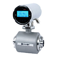
Negele FMI-C Operating Manual (76 pages)
Magnetic-inductive Flowmeter
Brand:
Negele
| Category:
Measuring Instruments
| Size: 1 MB
Table of Contents
Table of Contents
2
1 General Description
6
Structure and Identification of the Device
6
Function
6
Technical Data
7
Converter
7
Transmitter in Compact Design
7
Transmitter in Remote Design
8
Measuring Ranges and Error Limits
8
2 Safety Instructions
9
General Remarks
9
Special Diligence of the User
9
General Safety Instructions
10
Intended Use
11
Special Safety Instructions and Devices
11
Explanation of the Safety Symbols Used
12
3 Transport
13
General Information
13
Dimensions and Weight
14
Remote Version
14
Compact Version
14
Converter with Wall Bracket
15
Dimensions of the Process Connections
15
4 Application
16
Conditions Required for the Transmitter
16
Measuring of Air and Gas
16
Solids
16
Mounting Position - Electrode Axis
17
Inlet and Outlet Pipe Sections
20
Conductivity Conditions
20
Interference Fields
20
Earthing/Grounding Conditions
20
Meter Tube Lining
21
Flow Direction
21
Conditions Required for the Converter
22
Display Turned by 90
22
Alignment of the Converter
23
Cable Lengths for the Remote Version
23
Welding Work
24
Wire End Ferrule
24
5 Installation
25
Installation Instructions for the Transmitter
25
Installation Instructions for the Converter
26
Installation of the Electrical Power Supply
26
Connection of the Transmitter
29
Connection Scheme for the Remote Design
30
Screwed EMC Cable Gland
31
Electrical Connection of Peripherals
32
Digital Output
33
Digital Input
34
Analog Output - Current Output
34
CS3-Bus
35
6 Commissioning
36
General Information
36
Advice for Starting-Up the FMI
37
Basic Settings Upon Delivery
37
System Structure and Operating Elements
38
Flow Direction
39
Zero Point Adjustment ("ZERO Adjust")
39
Metering Interruption (Assignment of the Digital Input)
39
Metering with an Empty Meter Tube
39
Internal "EMPTY Pipe Detection
40
Metering at Low Conductivities
40
Optical Operating Elements
40
7 Operation
41
Basic Keypad Functions
42
Image Navigator
42
Zero Reset of the Volume Counter
45
How to Delete Malfunction Messages
45
Parameter Change
45
How to Release a Parameter Change
46
How to Release the Service Functions
46
Image Level: Measured Values
47
Measured Value: Volume
47
Measured Value: Flow Rate
47
Measured Value: Flow Rate and Volume
47
Measured Value: Total Quantity
47
Error Message: Transmitter Not Connected
48
Image Level: Base Parameters
48
Language
48
Cs3Bus Address
48
Dimension
49
Profibus Address
49
Q-Type
49
Image Level: Pulse Output
50
Pulse Mode
50
Pv1
51
Tp1
51
Pv2
51
Tp2
51
Image Level: Digital Input
52
Function: Digital Input
52
It1
52
Image Level: Current Output
52
Current Output Mode
53
Qmax
53
Tp3
53
Image Level: Metering Parameters
53
Lfs
54
Mspe
54
Bspe
54
Average
54
Offset
55
Span
55
Pipe Detect (Recognition of an Empty Meter Tube)
55
Nominal Width
55
Image Level: Special Functions
55
Zero Adjust
56
Factory Setting
56
Image Level: Service Level
56
Error Register: Metering
56
Error Register: Operating System
57
Simulation of the Current Output
57
Simulation of the Pulse Outputs
57
Simulation of the Flow Rate
58
Image Level: Info
58
Info1
58
Info2
58
Info3
59
8 Parameterization
60
Adjustments
63
Adjustment by Calibration Factor "M Spe
63
Measuring Accuracy
64
9 Troubleshooting
65
Error Diagnosis
65
Error Diagnosis Via the Display
65
Error List
66
Typical Effects or Error Sources
67
Flow Without Flow Rate Indication
67
No Pulse Transmission Despite Displayed Flow
67
No Analog Signal Available
67
Deviations of Measured Values
68
Error Reset
69
Transmitter Tests
69
Insulation Test
69
Symmetry Test
70
Visual Check
70
10 Maintenance
71
Safety Instructions for Maintenance Work
71
Routine Maintenance
71
Preventive Maintenance Steps
72
Repairs
73
Sending-In the Flow Meter to the Manufacturer
73
Repair Work
74
Replacement of the Sealing Cover of the Operating Unit
74
Replacement of the Transmitter
74
Special Program Functions
74
Flow Simulation
74
Simulation Via the Display Unit
75
Spare Parts to be Kept Available on Stock
75
11 Decommissioning
75
Temporary Decommissioning
75
Final Decommissioning / Disposal
75
12 Contact Details
76
Advertisement
Advertisement
Related Products
Negele FMI
Negele FMI-R
Negele Categories
Switch
Accessories
Measuring Instruments
Industrial Equipment
More Negele Manuals
Login
Sign In
OR
Sign in with Facebook
Sign in with Google
Upload manual
Upload from disk
Upload from URL