Sign In
Upload
Manuals
Brands
Navman Manuals
Control Unit
Jupiter 110
Navman Jupiter 110 Manuals
Manuals and User Guides for Navman Jupiter 110. We have
1
Navman Jupiter 110 manual available for free PDF download: Manual
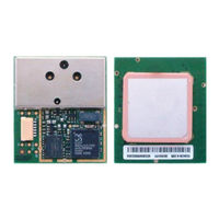
Navman Jupiter 110 Manual (17 pages)
Integrated GPS Sensor Module
Brand:
Navman
| Category:
Control Unit
| Size: 0.44 MB
Table of Contents
Related Documents
1
Table of Contents
2
Introduction
4
Technical Description
4
Receiver Architecture
4
Figure 2-1: Jupiter 110 Architecture
4
Major Components of the Jupiter 110
5
Product Applications
5
Physical Characteristics
5
Mechanical Specification
5
Environmental
5
Compliances
6
Marking/Serialisation
6
Figure 2-2: Application Example
6
Performance Characteristics
7
TTFF (Time to First Fix)
7
Hot Start
7
Warm Start
7
Cold Start
7
Acquisition Times
7
Battery Backup
7
Power Management
7
Tricklepower Mode
7
Table 3-1: Acquisition Times
7
Differential Aiding WAAS/EGNOS
8
Navigation Modes
8
Core Processor Performance
8
Dynamic Constraints
8
Position and Velocity Accuracy
8
Table 3-2: Jupiter 110 Processor Performance
8
Table 3-3: Position and Velocity Accuracy
8
Electrical Requirements
9
Power Supply
9
RF Sensitivity
9
Internal Patch Antenna
9
External RF Connector
9
Table 4-1: Operating Power for the Jupiter 110
9
Table 4-2: RF Sensitivity at Patch Antenna
9
Table 4-3: RF Sensitivity at External RF Connector
9
Data Input/Output Levels
10
Interfaces
10
External Antenna Connector
10
External Antenna Voltage
10
Table 4-4: Input/Output Voltage Levels
10
Table 5-1: External Antenna Characteristics
10
External I/O Connector
11
I/O Connector Signals
11
I/O Connector Description
11
Figure 5-1: Pinout I/O Connector
11
Table 5-2: Module I/O Pinouts
11
Table 5-3: I/O Connector Part Numbers
11
Software Protocol
12
NMEA Output
12
Navman NMEA Low Power Mode Messages
12
Low Power Configuration
12
Table 6-1: NMEA Default Settings
12
Table 6-2: Low Power Modes Message Values
12
Low Power Acquisition Configuration
13
Navman NMEA Active Antenna Status Message
13
Sirf Binary Output
13
Table 6-3: Low Power Acquisition Input Values
13
Table 6-4: Antenna Status Output Message Values
13
Mounting Option
14
Product Handling
14
Packaging and Delivery
14
ESD Sensitivity
14
Safety
14
Rohs Compliance
14
Disposal
14
Jupiter 110 Mechanical Layout
15
Figure 9-1: Jupiter 110 Mechanical Layout
15
Ordering Information
16
Glossary and Acronyms
16
Table 10-1: Jupiter 110 Ordering Information
16
Advertisement
Advertisement
Related Products
Navman Jupiter 110R
Navman Jupiter 110S
Navman Jupiter 110RS
Navman 12
Navman 11
Navman REPEAT 100
Navman Jupiter 32
Navman Jupiter 20
Navman Jupiter 11
Navman Jupiter 12
Navman Categories
GPS
Fish Finder
Car Navigation system
Measuring Instruments
Software
More Navman Manuals
Login
Sign In
OR
Sign in with Facebook
Sign in with Google
Upload manual
Upload from disk
Upload from URL