National Instruments 777687-20 Manuals
Manuals and User Guides for National Instruments 777687-20. We have 3 National Instruments 777687-20 manuals available for free PDF download: User Manual
National Instruments 777687-20 User Manual (159 pages)
Brand: National Instruments
|
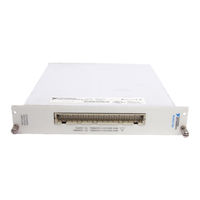
Category: Terminal Block
|
Size: 4 MB
Table of Contents
Advertisement
National Instruments 777687-20 User Manual (101 pages)
Brand: National Instruments
|
Category: Terminal Block
|
Size: 1 MB
Table of Contents
National Instruments 777687-20 User Manual (73 pages)
Eight-Channel Isolated Analog Input Module and Eight-Channel Wide Band Isolated Analog Input Module for Signal Conditioning
Brand: National Instruments
|
Category: I/O Systems
|
Size: 0 MB
Table of Contents
Advertisement
Advertisement
Related Products
- National Instruments 777687-02
- National Instruments 776572-81
- National Instruments 776572-21
- National Instruments 776572-1600
- National Instruments 776572-00
- National Instruments 776570-00
- National Instruments 779640-01
- National Instruments 779210-02
- National Instruments 779351-01
- National Instruments 778512-01