Sign In
Upload
Manuals
Brands
National Instruments Manuals
Switch
1128
National Instruments 1128 Manuals
Manuals and User Guides for National Instruments 1128. We have
1
National Instruments 1128 manual available for free PDF download: User Manual
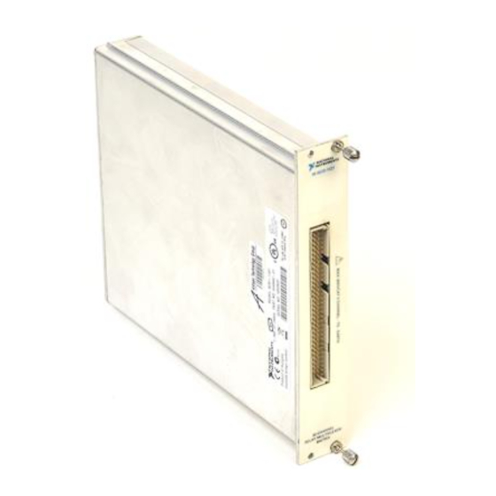
National Instruments 1128 User Manual (97 pages)
multiplexer kit
Brand:
National Instruments
| Category:
Switch
| Size: 3 MB
Table of Contents
User Manual
1
Scxi
3
Warranty
3
Canadian Department of Communications
5
Table of Contents
7
Chapter 1 Installing and Configuring the SCXI-1127/1128
11
Table 1-1. SCXI-1127/1128 Configurations
11
Installing the Software
12
Installing the Hardware
13
Installing the SCXI-1127/1128 Module into the SCXI Chassis
14
Figure 1-1. Installing the SCXI-1127/1128 into an SCXI Chassis
14
Connecting the SCXI-1127/1128 to the DMM in a Single-Chassis System
15
Single 4-Slot Chassis Configuration
16
Figure 1-2. 4-Slot Single-Chassis Installation
16
Figure 1-3. 4-Slot Configuration Parts Locator Diagram
17
Single 12-Slot Chassis Configuration
18
Figure 1-4. 12-Slot Single-Chassis Installation
18
Figure 1-5. 12-Slot Configuration Parts Locator Diagram
19
Connecting the SCXI-1127/1128 to the DMM in a Multichassis System
20
4-Slot and 4-Slot Multichassis Configuration
20
Figure 1-6. 4-Slot to 4-Slot Multichassis Configuration Parts Locator Diagram
21
4-Slot and 12-Slot Multichassis Configuration
22
Figure 1-7. 4-Slot to 12-Slot Multichassis Configuration Parts Locator Diagram
23
12-Slot and 12-Slot Multichassis Configuration
24
Figure 1-8. 12-Slot to 12-Slot Multichassis Configuration Parts Locator Diagram
25
Connecting the SCXI-1127/1128 to the DMM in a PXI-1010 Chassis
26
DMM in PXI Slots 1 through 7 Configuration
26
DMM in PXI Slot 8 Configuration
27
Connecting the SCXI-1127/1128 to the DMM in the PXI-1011 Chassis
27
DMM in PXI Slots 1 through 3 Configuration
28
DMM in PXI Slot 4 Configuration
28
Accessing the SCXI-1127/1128 through Other SCXI Modules Using a DAQ Device
28
Figure 1-9. Installing the SCXI-1127/1128 with Two DAQ Devices
29
Using a DAQ Device on a PXI-1010 Chassis
30
Using a DAQ Device on a PXI-1011 Chassis
30
Connecting the SCXI-1127/1128 to an External DMM
30
Configuring and Self-Test
32
Auto-Detecting Modules
32
Manually Adding Modules
33
Safety Information
34
Chapter 2 Using the SCXI-1127/1128
36
Operating as a Multiplexer/Scanner
36
Figure 2-1. SCXI-1331 Signal Connections
37
2-Wire Channel Scanning Configuration
38
Figure 2-2. 2-Wire Block Diagram
38
Figure 2-3. 2-Wire Wiring Diagram
39
1-Wire Channel Scanning Configuration
40
Figure 2-4. 1-Wire Block Diagram
40
4-Wire Channel Scanning Configuration
41
Figure 2-5. 1-Wire Wiring Diagram
41
Figure 2-6. 4-Wire Block Diagram
42
Figure 2-7. 4-Wire Wiring Diagram
43
4-Wire Versus 2-Wire Resistance Measurement
44
Figure 2-8. Signal Connections for a 2-Wire Resistance Measurement
44
Figure 2-9. Signal Connections for a 4-Wire Resistance Measurement
45
Mixed Mode Configuration
45
Hardware-Timed and Software Scanning
46
Figure 2-10. Mixed Mode Scanning with an SCXI-1331
46
Hardware-Timed Scanning
47
Figure 2-11. Hardware Scanning Flowchart
48
Figure 2-12. Cabling a DMM and Using the TRIG0 to Bus the VMC/EXT_TRIG_IN to Non-Cabled Modules
49
Hardware-Timed Scanning Using a DMM
49
Hardware-Timed Scanning Using External Instruments
49
Synchronous Scanning
49
Figure 2-13. Cabling an External DMM
50
Handshaking Scanning
50
Figure 2-14. Daisy-Chained for Handshaking
51
Figure 2-15. Connecting an External DMM to an SCXI-1127/1128 in an SCXI-2000 Series Chassis
51
Software Scanning
52
Making Temperature Measurements
52
Making Thermocouple Measurements
52
Figure 2-16. Temperature Measurement Wiring Diagram
53
Making RTD Measurements
54
Making Thermistor Measurements
54
Operating as a Matrix
55
32 × × × × 1 Matrix Configuration
55
Figure 2-17. 2 × 4, 1-Wire Matrix Configuration
55
Matrix Configuration
56
Figure 2-19. SCXI-1332 Terminal Block
57
Figure 2-20. SCXI-1332 Connected to an SCXI-1127
58
Matrix Expansion
59
Figure 2-21. SCXI-1332 Connected to an SCXI-1127/1128 Schematic
59
Figure 2-22. 8 8 Matrix Parts Locator Diagram
60
Figure 2-23. 8 × 8 Matrix Schematic
63
Independent Mode
64
Figure 2-26. SCXI-1127/1128 Relay Configuration
65
Input Characteristics
66
Specifications
66
Dynamic Characteristics
67
Trigger Characteristics
67
Figure C-1. Removing the SCXI Module Cover
74
Figure C-2. Bent and Trimmed Resistor
75
Front Connector
76
Figure D-1. SCXI-1127/1128 Front Connector Pin Assignments for 2-Wire Mode
77
SCXI-1127/1128 Front Connector Pin Assignments for 1-Wire Mode
77
SCXI-1127/1128 Front Connector Pin Assignments for 4-Wire Mode
77
Figure D-2. SCXI-1127/1128 Front Connector Pin Assignments for 1-Wire Mode
78
Figure D-3. SCXI-1127/1128 Front Connector Pin Assignments for 4-Wire Mode
79
An 4 × 8 Matrix
80
Table D-1. Front Connector Signal Description
81
Common Questions
82
SCXI-1127/1128 Configurations
83
Technical Support Resources
85
Worldwide Support
86
Advertisement
Advertisement
Related Products
National Instruments 1191
National Instruments 1192
National Instruments 187970E-01
National Instruments myDAQ 195509E-01L
National Instruments NI Vision 1752
National Instruments 199991x-02L
National Instruments 195315x-01L
National Instruments 192290x-01
National Instruments 156877x-01L
National Instruments NI Vision 1754
National Instruments Categories
Control Unit
I/O Systems
Controller
Computer Hardware
Measuring Instruments
More National Instruments Manuals
Login
Sign In
OR
Sign in with Facebook
Sign in with Google
Upload manual
Upload from disk
Upload from URL