Sign In
Upload
Manuals
Brands
NAiS Manuals
Control Unit
FPG-C32T2
NAiS FPG-C32T2 Manuals
Manuals and User Guides for NAiS FPG-C32T2. We have
1
NAiS FPG-C32T2 manual available for free PDF download: User Manual
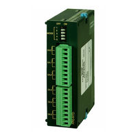
NAiS FPG-C32T2 User Manual (326 pages)
Applicable PLC
Brand:
NAiS
| Category:
Control Unit
| Size: 8.61 MB
Table of Contents
Table of Contents
2
Before You Start
9
Programming Tool Restrictions
12
Compatibility with the FP0
13
Chapter 1 Functions and Restrictions of the Unit
17
Unit Types
19
FPΣ Control Unit
19
FPΣ Expansion Unit
19
Units for FP0 and FPΣ
19
Communication Cassette
19
Restrictions on Unit Combinations
20
Restrictions on the Number of Expansion Units (for FP0 Expansion Unit)
20
Programming Tools
22
Tools Needed for Programming
22
Software Environment and Suitable Cable
22
Chapter 2 Specifications and Functions of Control Unit
24
Parts and Functions
26
Tool Port Specification
29
Communication Cassette
29
Input and Output Specifications
30
Input Specifications
30
Output Specifications
32
Terminal Layout Diagram
35
Control Unit (for C32T and C32T2)
35
Control Unit (for C24R2)
35
Chapter 3 Expansion
36
Type of Expansion Unit
38
Expansion Method of Units for FP0 and FPΣ
39
Expansion Method of FPΣ Expansion Unit
40
Specifications of FPΣ Expansion Unit
41
FPΣ Expansion I/O Unit
41
Chapter 4 I/O Allocation
44
I/O Allocation
46
I/O Number of FPΣ Control Unit
46
I/O Number of FPΣ Expansion Unit (for Left Side Expansion)
47
I/O Number of FP0 Analog I/O Unit (for Right Side Expansion)
48
I/O Number of FP0 I/O Link Unit (for Right Side Expansion)
49
Chapter 5 Installation and Wiring
52
Installation
52
Installation Environment and Space
52
Installation and Removal
55
Wiring of Power Supply
58
Grounding
60
Wiring of Input and Output
61
Input Wiring
61
Output Wiring
64
Precautions Regarding Input and Output Wirings
65
Wiring of MIL Connector Type
66
Wiring of Terminal Block Type
69
5.5 Wiring of Terminal Block Type
70
Safety Measures
71
Momentary Power Failures
72
Protection of Power Supply and Output Sections
72
Backup Battery
73
System Register Setting
74
Lifetime of Backup Battery
75
Chapter 6 High-Speed Counter and Pulse Output Functions
78
Overview of each Functions
78
Performance of Built- in High - Speed Counter
79
Function Specifications and Restricted Items
80
Table of Specifications
80
Function Being Used and Restrictions
82
Booting Time
84
High - Speed Counter Function
85
Overview of High - Speed Counter Function
85
Types of Input Modes
85
Min. Input Pulse Width
87
I/O Allocation
87
Instructions Used with High - Speed Counter Function
88
Sample Program
91
Pulse Output Function
95
Overview of Pulse Output Function
95
Types of Pulse Output Method
96
I/O Allocation
97
Control Mode
98
Instructions Used with Pulse Output Function
99
Sample Program for Positioning Control
118
PWM Output Function
131
Overview of PWM Output Function
131
Instruction Used with PWM Output Function
131
Chapter 7 Communication Cassette
136
Communication Functions of FPΣ
136
Functions of Communication Cassette
136
Communication Cassette
139
Type of Communication Cassette
139
Names and Principle Applications of the Ports
140
Chapter 8 Communication Function 1 Computer Link
140
Computer Link
140
Communication Specifications of Communication Cassette
141
Attachment of Communication Cassette
143
Wiring of Communication Cassette
144
Overview of Function
148
Explanation of Operation When Using a Computer Link
149
Format of Command and Response
150
Types of Commands that Can be Used
153
Setting the Communication Parameters When Using a Computer Link
155
Restriction
155
Connection Example with External Device
156
Connection Example with External Device (1:1 Communication with Computer)
156
Overview of 1:N Communication
163
Communication Cassette Used for 1:N Communication
163
Settings of System Register and Unit no
164
Connection with External Device
167
Chapter 9 Communication Function 2 General-Purpose
168
General - Purpose Serial Communication
168
Overview of Function
170
General - Purpose Serial Communication
170
Communication Parameter Settings When Using General - Purpose Serial Communications
173
Overview of Communication with External Devices
175
Data Transmission to External Device
175
Receiving Data from External Device
179
Connection Example with External Devices
183
Connection Example with External Device (1:1 Communication with Micro - Imagechecker)
183
General - Purpose Serial Communication
183
(1:1 Communication with FP Series PLC)
189
Data Transmitted and Received with the FPΣ
196
1:N Communication
198
Overview of 1:N Communication
198
Communication Cassette Used with 1 : N Communication
198
Setting of System Register
199
Flag Operations When Using Serial Communication
200
When "STX Not Exist" Is Set for Start Code and "CR" Is Set for End Code
200
When "STX" Is Set for Start Code and "ETX" Is Set for End Code
202
Changing the Communication Mode of COM. Port
204
Chapter 10 Communication Function 3 PLC Link Function
208
10.1 PLC Link
208
Overview of Function
208
10.2 Communication Parameter Settings
210
Setting of Communication Mode
210
Setting of Unit no
211
Allocation of Link Relay and Link Register
215
Setting the Largest Station Number for a PLC Link
221
10.3 Monitoring When a PLC Link Is Being Used
222
Monitoring Using Relays
222
10.4 Connection Example of PLC Link
223
Using a PLC Link with Three FPΣ Units
223
Sample Programs
226
PLC Link Response Time
227
Shortening the Transmission Cycle Time When There Are Stations that Have Not Been Added to the Link
230
Chapter 11 Other Functions
234
Analog Potentiometer
234
Clock/Calendar Function
235
Precautions Concerning Backup of Clock/Calendar Data
236
Example Showing the Clock/Calendar Being Used
237
Chapter 12 Self - Diagnostic and Troubleshooting
238
12.1 Self - Diagnostic Function
240
Operation on Error
241
12.2 Troubleshooting
242
Chapter 13 Specifications
250
13.1 Table of Specifications
252
I/O No. Allocation
259
13.3 Relays, Memory Areas and Constants
261
13.4 Table of System Registers
263
System Registers
263
Table of System Registers
265
13.5 Table of Special Internal Relays
270
13.6 Table of Special Data Registers
277
13.7 Table of Error Cords
291
Table of Syntax Check Error
291
Table of Self - Diagnostic Error
292
13.8 Table of Instructions
293
13.9 MEWTOCOL - COM Communication Commands
315
13.10 Hexadecimal/Binary/Bcd
316
13.11 ASCII Codes
317
13.12 Dimensions
318
13.12.1 Control Unit
318
13.12.2 Expansion Unit
319
Index
320
Record of Changes
324
Advertisement
Advertisement
Related Products
NAiS FPG-C32T
NAiS FPG-C24R2
NAiS FPS Series
NAiS FP Series
NAiS FP0-C10CRM
NAiS FP0-C32T
NAiS FP0-C32P
NAiS FP0-E16RS
NAiS FP0-E16YP
NAiS FP2-SDU
NAiS Categories
Controller
Monitor
Massager
Touch terminals
Timer
More NAiS Manuals
Login
Sign In
OR
Sign in with Facebook
Sign in with Google
Upload manual
Upload from disk
Upload from URL