Sign In
Upload
Manuals
Brands
Mycom Manuals
Air Compressor
V-Series
Mycom V-Series Manuals
Manuals and User Guides for Mycom V-Series. We have
1
Mycom V-Series manual available for free PDF download: Handling Manual
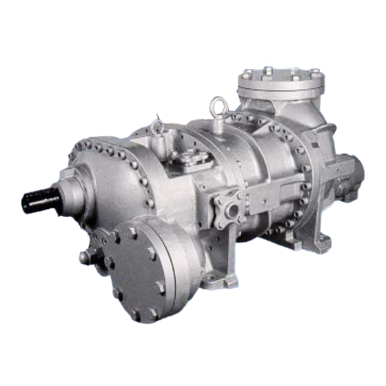
Mycom V-Series Handling Manual (62 pages)
Screw Refrigeration Compressor
Brand:
Mycom
| Category:
Air Compressor
| Size: 12 MB
Table of Contents
Contents
2
General Description of MYCOM V-Series Screw Compressor
3
Introduction
3
Refrigerant Compression Mechanism
4
Screw Compressor Cross Sectional View
4
Rotor Rotation & the Compression Cycle
4
Suction Phase
5
Compression Phase
5
Discharge Phase
5
Explanation of VI (Internal Volumetric Ratio)
6
Reasons for Adjusting VI
6
Variable VI Mechanism
7
Internal Volume Ratio
7
Relationship between Design and Operating Conditions
7
Conventional Screw Capacity Curve
8
External Adjustment of VI
9
VI Changing Rod Adjustment by Model
11
Precautions When Changing VI
11
VI Changing Procedures
12
Other Component Mechanisms
13
Oil Flow
14
Schematic Diagram of Lubrication System
14
Exploded View of V-Series Screw Compressor
15
Parts List
16
Longitudinal Assembly Drawing
18
External Dimensions
19
Table of Dimensions
20
Disassembly of V-Series
21
Preparations for Disassembly
21
Hand Tool Kit (Ref. Last Page)
21
Removing Compressor
21
Raising and Removing Compressor
22
Disassembly Sequence
22
Lifting the Compressor
22
Lower Cover Bolt
22
Mechanical Seal (100)
23
Exploded View of Mechanical Seal (100)
23
Cross Section of Mechanical Seal
23
Component Parts of Mechanical Seal Assembly
23
Seal Cover Portion
24
Removing Seal Cover (51)
24
Shaft Seal Cover (51)
24
Loosening Seal Collar Set Screws
24
A Oil Seal Sleeve
25
B Shaft Seal Assembly
25
Unloader Indicator
25
Removing Unloader Indicator Assembly
25
Removing Indicator Cover
26
Loosening Micro-Switch Set Plate Screws
26
Removing Micro-Switch Assembly
26
Removing Unloader Cover Bolts
26
Unloader Piston (64) and Unloader Cylinder
27
Cylinder Cam Mounting Portion
27
Unloader Indicator Cam Shaft Portion
27
Piston Lock Nut (69)
27
Blind Cover (22)
28
Checking Unloader Piston Cap Seal
28
Push Rod and O-Ring
28
Balance Piston and Balance Piston Sleeve
29
Exploded View of Balance Piston
29
Removing Stop Ring
29
Pulling out Balance Piston
29
Screwing in Position Detent Pin
30
After Screwing in Positioning Detent Pin
30
Balance Piston Sleeve Set Screw Portion
30
Bearing Cover
31
Removing Bearing Cover Bolts
31
Changing Rod Section
31
O-Ring for VI Changing Rod
31
Thrust Bearing
32
Bearing Gland Bolt and Lock Washer
32
After Thrust Bearing Gland Removed
32
Drawing out Thrust Bearing
33
Set of Thrust Bearing (L Side Lies on R Side)
33
Stamps on Thrust Bearing Gland
33
Thrust Bearing Portion of Models 160V**~200V**
33
Suction Cover and Side Bearing
34
O-Ring Gland
35
Rotors
35
Pulling out Rotors
35
Pulling out M Rotor
36
Removing Lock Washer Bolt
36
Pulling out Variable VI Slide Valve Changing Rod
36
Pulling out Unloader Slide Valve
36
Bearing Head and Main Bearing
37
Bearing Positioning Spring Pin
38
Fitting Bearing
38
Applying Oil to Gasket
38
Unloader Slide Valve and Portion
39
Mounting Unloader Slide Valve
39
Mounting Variable VI Slide Valve
39
Mounting Bearing Head and Rotor Casing
39
Fitting VI Slide Valve Lock Washer
40
Rotor Casing and Rotors
40
Suction Cover
40
Stamp Marks on Lobe Edges
40
Positioning Side Bearing
41
O-Ring Retainer
41
Fitting Suction Cover
41
Suction Cover Assembled
41
Thrust Bearing Mounting Side
42
Mounting Order of Thrust Bearing
42
Mounting Direction
42
Spacer
42
Tightening Thrust Bearing Tightening Washer
43
A Measuring End Clearance
43
End Clearance (Discharge Side)
43
Adjusting End Clearance
44
Second Method
44
When the End Clearance Is Smaller than the Specified Value
44
Determining Axial Deflection
45
VI Changing Rod and Thrust Washer
45
Full View of Bearing Cover
46
Unloader Cylinder and Blind Cover
47
Unloader Cylinder
47
Unloader Cover
47
Mounting Unloader Cover
48
Exploded View of Unloader Cover
48
Mechanical Shaft Seal
48
O-Ring
48
Mounting Carbon Insert
49
Seal Cover
49
Plug for Model 160V** Seal Collar
49
Disassembly and Adjustment of Unloader Indicator
50
System with Two Micro-Switches
50
No-Load Cam Adjustment
53
Adjustment of Potentiometer at No-Load Position
54
Groove in Micro-Switch Cam
54
Potentiometer Shaft
54
Potentiometer
54
Standards of Components
55
End Clearance
55
Mechanical Seat Assemblies by Compressor Model
55
Bolt Sizes
55
Bolt Fastening Torque
56
Thrust Bearing Gland Fastening Bolt Torque
56
Lock Nut
56
Lock Nut Fastening Torque
56
Stop Rings
57
O-Ring List
57
Compressor Oil
58
Selection of Compressor Oil
58
Changing Compressor Oil Brands
58
Gasket List
59
Usability Limits of V-Series Screw Compressors
60
Theoretical Displacement
60
Connecting Port Diameters
60
Hand Tool Kit
61
Advertisement
Advertisement
Related Products
mycom 125LUD
mycom 125SUD
mycom 160LUD
mycom 160MUD
mycom 160SUD
mycom 160VLD
mycom 160VLG
mycom 160VMD
mycom 160VMG
mycom 160VSD
Mycom Categories
Air Compressor
Engine
Compressor
Cell Phone
Control Unit
More Mycom Manuals
Login
Sign In
OR
Sign in with Facebook
Sign in with Google
Upload manual
Upload from disk
Upload from URL