Sign In
Upload
Manuals
Brands
MSA Manuals
Controller
General Monitors 4802A
MSA General Monitors 4802A Manuals
Manuals and User Guides for MSA General Monitors 4802A. We have
1
MSA General Monitors 4802A manual available for free PDF download: Manual
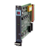
MSA General Monitors 4802A Manual (68 pages)
Control Module
Brand:
MSA
| Category:
Controller
| Size: 2 MB
Table of Contents
Table of Contents
2
Model 4802A
3
Warranty Statement
6
Special Warnings
6
System Integrity Verification
7
Quick-Start Guide
9
Control Module Installation
9
Figure 1: Control Module Coding Strip
9
Rear Terminal Connections
10
Figure 2: Wire Strip Length
10
Figure 3: Rear Terminal Designations
10
Sensor Connections
11
Applying Power
11
Figure 4: Sensor/Controller Connections
11
Table 1: Terminal Designations for Sensor Wires
11
Figure 5: Rear Power Connections
12
Introduction
13
General Description
13
Figure 6: Model 4802A
13
Features & Benefits
14
Applications
15
Installation
16
Upon Receipt of Equipment
16
Control Module Installation
16
Figure 7: Control Module Coding Strip
16
Rear Terminal Connections
17
Figure 8: Wire Strip Length
17
Figure 9: Rear Terminal Designations
17
A2 Alarm
18
A1 Alarm
18
Table 2: Terminal Designations for A2 Alarm Outputs
18
Table 3: A2 Alarm Relay Contacts
18
Table 4: Terminal Designations for A1 Alarm Outputs
18
Fault Alarm
19
Figure 10: Recommended Relay Protection Circuits
19
Table 5: A1 Alarm Relay Contacts
19
Table 6: Terminal Designations for Fault Outputs
19
Other Open Collector Outputs
20
Figure 11: Open Collector External Circuits
20
Table 7: Terminal Designations for Un-Accept and Calibration/Inhibit Mode
20
Sensor Connections
21
Card Test Switch
21
Figure 12: Sensor/Controller Connections
21
Figure 13: Switch Connections for Card Test Feature
21
Table 8: Terminal Designations for Sensor Wires
21
Analog Output Signal
22
Figure 14: Analog Signal Connections
22
Table 9: Terminal Designations for Analog Output
22
Sensor Location Considerations
23
General Sensor Location Considerations
23
Figure 15: Power Connections
23
Sensor Poisons
24
Applying Power
24
Operation
25
General Maintenance
25
Field Calibration
25
Electrical Inputs
26
Electrical Outputs
26
Table 10: Rear Terminal Relay Contacts
26
Accepting Alarm Conditions
27
Resetting Latched Alarms
28
LED Test
28
CAL/INH Open Collector
28
Card Test Feature
28
Fault Diagnostics
29
Table 11: Fault Codes
30
User Interfaces
31
Types of User Interfaces
31
Figure 16: Front Panel Display
31
Calibration Check Mode
32
Figure 17: Portable Purge Calibrator
32
Figure 18: Entering CAL Check Mode
32
Calibration Mode
33
Figure 19: Portable Purge Calibrator
34
Figure 20: Entering CAL Mode
34
Figure 21: AC Display During CAL Mode
35
Figure 22: CP Display During CAL Mode
35
Figure 23: CC Display During CAL Mode
36
Figure 24: F7 Display During CAL Mode
36
Setup & Setup Check Modes
37
Entering the Password
38
Figure 25: Entering Setup and Setup Check Modes
38
Inhibit Mode
39
Figure 26: Entering the Password
39
Figure 27: Entering Inhibit Mode
39
A2 Alarm Options
40
Figure 28: Energized/De-Energized Alarm Option
40
Figure 29: A2 Latching/Non-Latching Alarm Option
40
A1 Alarm Options
41
Figure 30: A2 Alarm Set Point Option
41
Figure 31: A1 Energized-De-Energized Alarm Option
42
Figure 32: A1 Latching/Non-Latching Alarm Option
42
Calibration Level Option
43
Figure 33: A1 Set Point Option
43
Figure 34: Calibration Level
43
Fault/Inhibit Option
44
Figure 35: Fault / Inhibit Option
44
Figure 36: Entering Card Test Options
44
Card Test Options
45
Figure 37: Card Test Ramp Time
45
Figure 38: Alarm Output During a Card Test
45
Password Options
46
Figure 39: Password Enabled/Disabled Option
46
Inhibit Mode
47
Figure 40: Entering a New Password
47
Setup Mode Selection Block Diagram
48
Table 12: Setup Display Options
48
Customer Support
49
General Monitors' Offices
49
Table 13: GM Locations
49
Appendix
50
Principle of Operation
50
Figure 41: Catalytic Sensor Diagram
50
Spare Parts and Accessories
51
Sensors
51
Sensor Housing
51
Splash-Guard & TGA-1
52
Figure 42: Universal Sensor Housing with Sensor and Splash-Guard
52
Figure 43: Splash-Guard Picture
52
Dust Guard Assembly
53
Figure 44: Dust Guard Picture
53
Figure 45: Dust Guard Assembly Kit Picture
53
Duct Mounting Plates
54
Calibration Equipment
54
Figure 46: Duct Mounting Plate, Assembly Drawing
54
Figure 47: Portable Purge Calibrator
55
Figure 48: 3-Liter Chamber
55
Calibration Check Mode
56
Calibration Mode
56
Calibration Check & Calibration Modes
57
Calibration Equipment and Part Numbers
57
System Specifications
58
Converting Test and Calibration Gas Concentrations for % LFL to % Volume
58
Accuracy
58
Relative Sensitivities
59
Poisons and Interfering Gases
59
Storage
59
Mechanical Specifications
59
Electrical Specifications
60
Cable Parameters
60
Table 14: Recommended Maximum Cable Lengths between Module & Sensor
60
Table 15: Maximum Allowable Cable Lengths between Analog Output Connections
60
Environmental Specifications
61
Engineering Specifications
61
Zero Two System
61
4802A Control Module
62
Volatile Liquids and Solvents
63
Engineering & Technical Drawings
65
Outline & Terminal Connections
65
Figure 49: Outline and Terminal Connections 4802A
65
Final Assembly
66
Figure 50: Final Assembly, 4802A
66
Zero Two Series Modules
67
Advertisement
Advertisement
Related Products
MSA altair 4
MSA altair 4x
MSA ALTAIR 4XR
MSA AirElite 4h
MSA 47K-HT-PRP
MSA Advantage 4000 Series
MSA Advantage 4100
MSA Advantage 410 S
MSA Advantage 410 L
MSA 415865
MSA Categories
Safety Equipment
Respiratory Product
Security Sensors
Gas Detectors
Measuring Instruments
More MSA Manuals
Login
Sign In
OR
Sign in with Facebook
Sign in with Google
Upload manual
Upload from disk
Upload from URL