Sign In
Upload
Manuals
Brands
MRV Communications Manuals
Multiplexer
LambdaDriver 800
MRV Communications LambdaDriver 800 Manuals
Manuals and User Guides for MRV Communications LambdaDriver 800. We have
1
MRV Communications LambdaDriver 800 manual available for free PDF download: User Manual
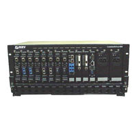
MRV Communications LambdaDriver 800 User Manual (207 pages)
Wavelength Division Multiplexer
Brand:
MRV Communications
| Category:
Multiplexer
| Size: 24 MB
Table of Contents
Contact Information
2
Table of Contents
3
About this Manual
15
Audience
15
Latest Revision
15
Related Documents
15
Organization
15
Typographical Conventions
16
Acronyms
16
Safety Requirements
18
Before Installing
18
Before Powering on
18
During Operation
19
Servicing
19
Chapter 1 Overview
20
Function
20
Advantages
20
Features
20
Application
21
Installation
21
Operation
21
Management
21
Architecture
21
Components
22
Chassis
22
Features
22
Figure 1: LD400 Chassis Layout
22
Figure 2: LD800 Chassis Layout
22
Layout
22
Overview
22
Transponder Module
23
Overview
23
Features
24
Models
24
Figure 3: TM-SFP Single Transponder Module Layout
25
Figure 4: TM2-SFP Dual Transponder Module Layout
25
Layout
25
Figure 5: TM-DXFP 10 Gbps Transponder Module Layout
26
Product Specification
27
Mux Module
32
Overview
32
Features
32
Layout
32
Figure 6: Mux Module Layout
32
Product Specification
33
Demux Module
34
Overview
34
Features
34
Layout
34
Figure 7: Demux Module Layout
34
Product Specification
35
Management Module
36
Overview
36
Features
36
Layout
36
Figure 8: Management Module Layout
36
Product Specification
37
Service Module
38
Overview
38
Features
38
Models
38
Layout
39
Figure 9: Single Service Module Layout
39
Figure 10: Dual Service Module Layout
39
Product Specification
40
1+1 Redundancy Module
44
Overview
44
Features
44
Layout
45
Figure 11: 1+1 Redundancy Module with Service Functionality Layout
45
Figure 12: 1+1 Redundancy Module Without Service Functionality Layout
45
Product Specification
46
OADM Module
48
Overview
48
Features
48
Layout
49
Figure 13: Single-Interface OADM Module Layout
49
Figure 14: Dual-Interface OADM Module Layout
49
Product Specification
50
OA Module
51
Overview
51
Features
52
Layout
52
Figure 15: OA Module Layout
52
Product Specification
53
ESCON Multiplexer Module
55
Overview
55
Features
56
Layout
56
Figure 16: ESCON Module Layout
56
Product Specification
57
GM2 Gigagbit Ethernet Multiplexer Module
58
Overview
58
Features
59
Models
59
Layout
60
Figure 17: EM2009-GM2 Module Layout
60
Figure 18: TM-GM2 Module Layout
60
Product Specification
61
AC Primary Power Supply Module
63
Features
63
Overview
63
Figure 19: LD400 AC Power Supply Module Layout
64
Figure 20: LD800 AC Power Supply Module Layout
64
Layout
64
DC Primary Power Supply Module (Optional)
65
Features
65
Figure 21: LD400 DC Power Supply Module Layout
65
Layout
65
Overview
65
AC Redundant Power Supply Module (Optional)
66
DC Redundant Power Supply Module (Optional)
66
Fan Module
66
Features
66
Figure 22: LD800 DC Power Supply Module Layout
66
Overview
66
Blank Panel Module
67
Layout
67
Overview
67
Channels
67
Cwdm
67
Figure 23: Blank Panel Module Layout
67
Dwdm
68
Table 1: CWDM Channels - Nominal Central Wavelengths
68
Table 2: DWDM Channels - Numbers, Frequencies, and Wavelengths
68
Chapter 2 Applications
69
General
69
Point-To-Point Network Topologies
69
Regular Point-To-Point
69
Cabling
69
Hardware
69
Scope
69
Data Flow
70
Link-Protected Point-To-Point
70
Figure 24: Regular Point-To-Point with up to 8 Full-Duplex Channels
70
Hardware
70
Scope
70
Cabling
71
Data Flow
71
Figure 25: Link Protected Point-To-Point with up to 8 Full-Duplex Channels
71
Single-Fiber Point-To-Point
72
Cabling
72
Data Flow
72
Hardware
72
Scope
72
Ring Network Topologies
73
Single-Fiber Ring
73
Cabling
73
Figure 26: Single-Fiber Point-To-Point with up to 4 Full-Duplex Channels
73
Hardware
73
Scope
73
Data Flow
74
Central Office Ring
75
Figure 27: Single-Fiber Ring with up to 8 Full-Duplex Channels
75
Scope
75
Cabling
76
Data Flow
76
Hardware
76
Figure 28: Central Office Ring with up to 8 Full-Duplex Channels
77
Star Network Topology
78
Scope
78
Hardware
78
Cabling
78
Inter-Ldx00 Cabling
78
Intra-Ldx00 Cabling
78
Data Flow
79
CO Ldx00
79
Left BO Ldx00
79
Right BO Ldx00
79
Figure 29: Star with up to 4 Full-Duplex Channels
80
Multipoint Network Topologies
81
Regular Multipoint
81
Cabling
81
Data Flow
81
Hardware
81
Scope
81
Repeated-Channel-Use Multipoint
82
Figure 30: Multipoint with up to 8 Full-Duplex Channels
82
Escon
83
Figure 31: Repeated Channel Use Multipoint with up to 16 Full-Duplex Channels
83
Outband Topologies
83
Table 3: Outband Operating Ranges for ESCON Multiplexer
84
Figure 32: ESCON Outband Point-To-Point Topology
85
Figure 33: ESCON Outband Star Topology
87
Inband Topologies
87
Table 4: Inband Medium Operating Ranges for ESCON Multiplexer
88
Figure 34: ESCON Inband Medium Range Point-To-Point Topology
89
Table 5: Inband Long Operating Ranges for ESCON Multiplexer
89
Gm2
91
Figure 35: ESCON Inband Long-Range Point-To-Point Topology
91
Outband Topologies
91
Figure 36: GM2 Outband Point-To-Point Topology
92
Figure 37: GM2 Outband Star Topology
94
Inband Topology
94
Figure 38: GM2 Inband Point-To-Point Topology
96
Rules for Network Topologies
97
Chapter 3 Installation
100
General
100
Safety
100
Package Contents
100
Essentials
100
Options
100
Requirements
100
Tools
101
Mounting
101
Chassis
101
Transponders
101
Environmental
101
Power
101
Grounding
102
Networking
102
Management
102
Multiplexing
102
Procedure
103
Configuration
103
Table 6: JP6 Jumper Positioning
103
Table 7: JP7 Jumper Positioning
103
TM-SFP Single Transponder Module
103
Table 8: JP8 Jumper Positioning
104
Table 9: JP9 Jumper Positioning
104
Figure 39: DIP Switch Location on TM-SFP Transponder Module
105
Table 10: JP1 Jumper Positioning
105
TM2-SFP Dual Transponder Module
105
Table 11: JP2 Jumper Positioning
106
Table 12: JP4 and JP5 Jumpers Positioning
106
Figure 40: DIP Switch Location on TM2-SFP Transponder Module
107
Table 13: DIP Switch (SW1 or SW2) Setting of TM-SFP or TM2-SFP Transponder Module
108
Table 14: JP2 Jumper Positioning
109
TM-DXFP 10 Gbps Transponder Module
109
Table 15: DIP Switch SW1 Setting of TM-DXFP Transponder Module
110
ESCON Module
111
Figure 41: DIP Switch Location on TM-DXFP Transponder Module
111
Figure 42: DIP Switch Location on ESCON Module
112
Mounting
113
Chassis
113
Modules
113
Table 16: DIP Switch Setting of ESCON Module
113
Cabling
115
Figure 43: Mux to Demux Cabling between Ldx00S
115
Module to Module
115
Figure 44: Demux to Demux Cabling between Ldx00S
116
Figure 45: Single-Interface OADM to Single-Interface OADM Cabling in an Ldx00
116
Figure 46: Dual-Interface OADM to Dual-Interface OADM Cabling in an Ldx00
117
Figure 47: Single-Interface OADM to Single-Interface OADM Cabling between Ldx00S
117
Figure 48: Dual-Interface OADM to Dual-Interface OADM Cabling between Ldx00S
118
Figure 49: Single-Interface OADM to Service Cabling in an Ldx00
118
Figure 50: Single-Interface OADM to 1+1 Cabling in an Ldx00
119
Figure 51: Single-Interface OADM to Mux Cabling between Ldx00S
119
Figure 52: Single-Interface OADM to Demux Cabling between Ldx00S
120
Figure 53: Service to Service Cabling between Ldx00S
120
Figure 54: 1+1 to 1+1 Cabling between Ldx00S
121
Figure 55: Transponder to Mux Cabling in an Ldx00
121
Figure 56: Transponder to Demux Cabling in an Ldx00
122
Figure 57: Transponder to OADM Cabling in an Ldx00
122
Figure 58: Mux/Demux to Service Cabling in an Ldx00
123
Figure 59: Mux/Demux to 1+1 Cabling in an Ldx00
123
Figure 60: Service to Mgt Cabling in an Ldx00
124
Figure 61: 1+1 to Mgt Cabling in an Ldx00
124
Figure 62: ESCON-To-Transponder Cabling in or between Ldx00S
125
Figure 63: ESCON-To-Mux Cabling in or between Ldx00S
125
Figure 64: ESCON-To-Demux Cabling in or between Ldx00S
126
Figure 65: ESCON-To-ESCON Cabling between Ldx00S
126
Figure 66: Pre-Amplifier OA to Demux Cabling in Ldx00
127
Figure 67: Pre-Amplifier OA to Single-Interface OADM Cabling in Ldx00
127
Figure 68: Pre-Amplifier OA to Dual-Interface OADM Cabling in Ldx00
128
Figure 69: Mux to Booster OA Cabling in Ldx00
128
Figure 70: Single-Interface OADM to Booster OA Cabling in Ldx00
129
Figure 71: Dual-Interface OADM to Booster OA Cabling in Ldx00
129
Figure 72: Single-Interface OADM to In-Line OA to Single-Interface OADM Cabling in Ldxs00
130
Figure 73: Dual-Interface OADM to In-Line OA to Dual-Interface OADM Cabling in Ldxs00
130
Figure 74: GM2-To-Transponder Cabling in an Ldx00
131
Figure 75: GM2-To-Mux Cabling in an Ldx00
131
Access Ports
132
Figure 76: GM2-To-Demux Cabling in an Ldx00
132
Figure 77: GM2-To-GM2 Cabling between Ldx00S
132
Figure 78: ASCII Terminal/Emulator Connection to Ldx00 Directly
133
Figure 79: TELNET Station Connection to Ldx00
133
Management Ports
133
Power Line Connection
134
Chapter 4 Startup, Setup, and Operation
135
Startup
135
Setup
135
Default Settings
135
Table 17: Default Settings
135
Custom Settings
136
Operation
136
Table 18: Front Panel Leds
137
Chapter 5 CLI Management
139
General
139
Functions
139
Management Station Connection
139
Management Station Setup
139
ASCII Terminal/Emulator Setup
139
TELNET Station Setup
139
Table 19: ASCII Terminal/Emulator Setup for CLI Management
139
Password
140
CLI Types
140
CLI Access
140
CLI Commands
141
General
141
Table 20: Function of Symbols in CLI Commands
141
Global Commands
142
Module-Specific Commands
142
Table 21: CLI Commands Per Module
142
Specification
143
Console
143
System
148
Snmp (in Operational CLI Only)
154
Slot
156
Statistics (in Operational CLI Only)
163
Appendix A: Software Upgrading/Downloading
165
General
165
Procedure
165
Requirements
165
Interconnection
165
Setup
165
Appendix B: Troubleshooting
167
Table 22: Startup and Operation Troubleshooting
167
Appendix C: Loopback Tests
172
General
172
Transponders
172
Hardware/Software Control
172
RLB Test
172
Data Path
172
Figure 80: Data Path in RLB Test Using a Transponder
172
Purpose
172
Table 23: Transponder RLB and LLB Control by Software and Hardware
172
Preparation
173
Interconnection
177
Procedure
177
LLB Test
177
Data Path
177
Figure 81: RLB/LLB Test Network Topology Using Transponders
177
Purpose
177
Figure 82: Data Path in LLB Test Using a Transponder
178
Preparation
178
Interconnection
179
Procedure
179
Gm2S
180
RLB Test
180
Data Path
180
Figure 83: Data Path in RLB Test Using a GM2
180
Preparation
180
Purpose
180
Figure 84: RLB/LLB/TLB Test Network Topology Using Gm2S
181
Interconnection
181
Procedure
181
LLB Test
182
Data Path
182
Figure 85: Data Path in LLB Test Using a GM2
182
Interconnection
182
Preparation
182
Procedure
182
Purpose
182
TLB Test
183
Data Path
183
Figure 86: Data Path in TLB Test Using a GM2
183
Interconnection
183
Preparation
183
Procedure
183
Purpose
183
Appendix D: Cable Wiring
184
Figure 87: Null-Modem RS-232 Cable Wiring
184
Figure 88: Modem RS-232 Cable Wiring
184
Figure 89: Ethernet Straight Cable Wiring
185
Figure 90: Ethernet Cross Cable Wiring
185
Appendix E: Cleaning Optical Connectors
186
General
186
Tools and Equipment
186
Procedure
186
Appendix F: Modem Setup and Installation
187
General
187
Requirements
187
Ldx00 Side
187
Management Side
187
Setup
187
Installation
187
Figure 91: ASCII Terminal/Emulator Connection to Ldx00 Via Modem
188
Appendix G: Replacing a Module
189
General
189
Tools
189
Procedure
189
Network Module
189
Power Supply Module
189
SFP Module
189
Appendix H: Servicing the Fan Module
191
Tools
191
Procedure
191
Ld400
191
Ld800
191
Appendix I: Redundancy Protection Networks
192
General
192
Topologies
192
Point-To-Point with Inclusive End-To-End Total Redundancy
192
Lambdadriver
192
Ring with Inclusive End-To-End Total Redundancy
193
Figure 92: Point-To-Point with Inclusive End-To-End Total Redundancy
193
Lambdadriver
193
Point-To-Point with Exclusive End-To-End Total Redundancy
194
Figure 93: Ring with Inclusive End-To-End Total Redundancy
194
Ring with Exclusive End-To-End Total Redundancy
195
Figure 94: Point-To-Point with Exclusive End-To-End Total Redundancy
195
Point-To-Point with Fiber-Only Redundancy
196
Figure 95: Ring with Exclusive End-To-End Total Redundancy
196
Ring with Fiber-Only Redundancy
197
Figure 96: Point-To-Point with Fiber-Only Redundancy
197
Figure 97: Ring with Fiber-Only Redundancy
198
Installation
198
Appendix J: Product Specification
200
(Sfps)
204
Appendix K: Small Form-Factor Pluggables
204
Glossary
207
Advertisement
Advertisement
Related Products
MRV Communications LambdaDriver 400
MRV Communications MM 04
MRV Communications MULTI VOICE 4
MRV Communications Categories
Switch
Media Converter
Server
Network Hardware
Multiplexer
More MRV Communications Manuals
Login
Sign In
OR
Sign in with Facebook
Sign in with Google
Upload manual
Upload from disk
Upload from URL