Sign In
Upload
Manuals
Brands
MR Manuals
Industrial Electrical
VACUTAP VM-Ex
MR VACUTAP VM-Ex Manuals
Manuals and User Guides for MR VACUTAP VM-Ex. We have
1
MR VACUTAP VM-Ex manual available for free PDF download: Installation And Commissioning Instructions
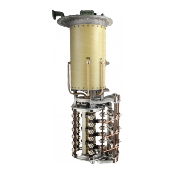
MR VACUTAP VM-Ex Installation And Commissioning Instructions (210 pages)
On-load tap-changer
Brand:
MR
| Category:
Industrial Electrical
| Size: 18 MB
Table of Contents
Table of Contents
3
Introduction
7
Manufacturer
7
Completeness
7
Safekeeping
7
Notation Conventions
7
Hazard Communication System
7
Information System
9
Instruction System
9
Safety
11
Appropriate Use
11
Inappropriate Use
12
Fundamental Safety Instructions
12
Standards and Regulations
14
Application Range of the On-Load Tap-Changer
14
Standards and Regulations
16
Measures for Ensuring Compliance with Explosion Protection Requirements
17
Measures Taken by the Manufacturer
17
Measures to be Taken by the Transformer Manufacturer/Operator
17
Personnel Qualification
20
Personal Protective Equipment
22
Product Description
23
Scope of Delivery
23
On-Load Tap-Changer
23
Function Description
23
Setup/Models
24
Nameplate and Serial Number
28
Protective Devices
28
Drive Shaft
31
Function Description
31
Design/Model
33
Identification Plate
35
Packaging, Transport and Storage
36
Packaging
36
Suitability
36
Markings
37
Transportation, Receipt and Handling of Shipments
37
Storage of Shipments
38
Unpacking Shipments and Checking for Transportation Damages
39
Mounting
40
Installation Information
40
Preparatory Work
41
Fitting Mounting Flange on Transformer Cover
41
Fitting Stud Bolts on Mounting Flange
41
Installing the On-Load Tap-Changer in the Transformer (Standard Version)
42
Fastening On-Load Tap-Changer to Transformer Cover
42
Fastening VACUTAP® VM 300 to Transformer Cover
50
Connecting the Tap Winding and On-Load Tap-Changer Take-Off Lead
53
Performing Transformer Ratio Test before Drying
63
Performing DC Resistance Measurement on Transformer
64
Drying On-Load Tap-Changer in Autoclave
64
Drying On-Load Tap-Changer in Transformer Tank
66
Filling the Oil Compartment of the On-Load Tap-Changer with Insulating Fluid
80
Performing Transformer Ratio Test after Drying
81
Installing On-Load Tap-Changer in Transformer (Bell-Type Tank Version)
82
Inserting On-Load Tap-Changer into Supporting Structure
82
Connecting the Tap Winding and On-Load Tap-Changer Take-Off Lead
90
Performing Transformer Ratio Test before Drying
100
Performing DC Resistance Measurement on Transformer
101
Drying On-Load Tap-Changer in Autoclave
101
Lifting Top Part of On-Load Tap-Changer Head off Supporting Flange (Bottom Part)
103
Attaching the Bell-Type Tank and Connecting the On-Load Tap-Changer to the Top Part of the On-Load Tap-Changer Head
111
Drying On-Load Tap-Changer in Transformer Tank
122
Filling the Oil Compartment of the On-Load Tap-Changer with Insulating Fluid
136
Performing Transformer Ratio Test after Drying
137
Fitting Protective Devices and Drive Components
138
Electrically Connecting the Temperature Sensor
138
Installing Protective Relay in Piping and Connecting
138
Fitting Motor-Drive Unit
148
Fitting Drive Shaft
148
Centering On-Load Tap-Changer and Motor-Drive Unit
172
Making the Electrical Connections for the Motor-Drive Unit
172
Commissioning
173
Commissioning the On-Load Tap-Changer at the Transformer Manufacturer's Site
173
Bleeding On-Load Tap-Changer Head and Suction Pipe
173
Grounding the On-Load Tap-Changer
175
Checking Motor-Drive Unit
176
High-Voltage Tests on the Transformer
177
Transporting Transformer to the Operating Site
178
Transport with Drive Removed
178
Transport with Full Transformer Tank and Without Oil Conservator
178
Transport with Empty Transformer Tank
179
Commissioning Transformer at Operating Site
180
Filling the Oil Compartment of the On-Load Tap-Changer with Insulating Fluid
180
Bleeding On-Load Tap-Changer Head and Suction Pipe
181
Checking Motor-Drive Unit
183
Checking Protective Relay
184
Commissioning the Transformer
185
Fault Elimination
186
Tripping the Protective Relay and Re-Commissioning the Transformer
188
Flap Valve in OPERATION Position
188
Flap Valve in off Position
189
Re-Commissioning the Transformer
189
Technical Data
190
Permissible Ambient Conditions
190
Technical Data for Protective Relay
190
Protective Relay with Several Dry-Reed Magnetic Switches
192
Limit Values for Dielectric Strength and Water Content of Insulating Fluids
193
Drawings
194
VACUTAP® VM, Installation Drawing (746230)
194
VACUTAP® VM 300, Installation Drawing (765192)
196
VACUTAP® VM, Installation Position of Selector Connection Contacts (890477)
197
Special Design for Bell-Type Tank Installation for um up to 300 Kv (896762)
198
Lifting Traverse for Bell-Type Tank Installation (890180)
199
On-Load Tap-Changer Head (893899)
200
On-Load Tap-Changer Head with Tap-Change Supervisory Control (894109)
201
Pipe Connection Q with Tap-Change Supervisory Control (766161)
202
Tracing Template for On-Load Tap-Changer Head (890183)
203
Socket Wrench for Kerosene Drain Plug (890182)
204
Screw Tools for Installation and Maintenance (890478)
205
Bevel Gear CD 6400, Dimensional Drawing (892916)
206
Glossary
207
Advertisement
Advertisement
Related Products
MR VACUTAP VM Series
MR VACUTAP VMS
MR VACUTAP VM
MR VACUTAP VV-Ex Series
MR VACUTAP VR
MR VACUTAP VR I HD-Ex
MR VACUTAP VR Series
MR VACUTAP VRC-Ex
MR VACUTAP VRE-Ex
MR VACUTAP VRD-Ex
MR Categories
Industrial Equipment
Controller
Measuring Instruments
Thermometer
Control Systems
More MR Manuals
Login
Sign In
OR
Sign in with Facebook
Sign in with Google
Upload manual
Upload from disk
Upload from URL