Sign In
Upload
Manuals
Brands
Moseley Manuals
Radio
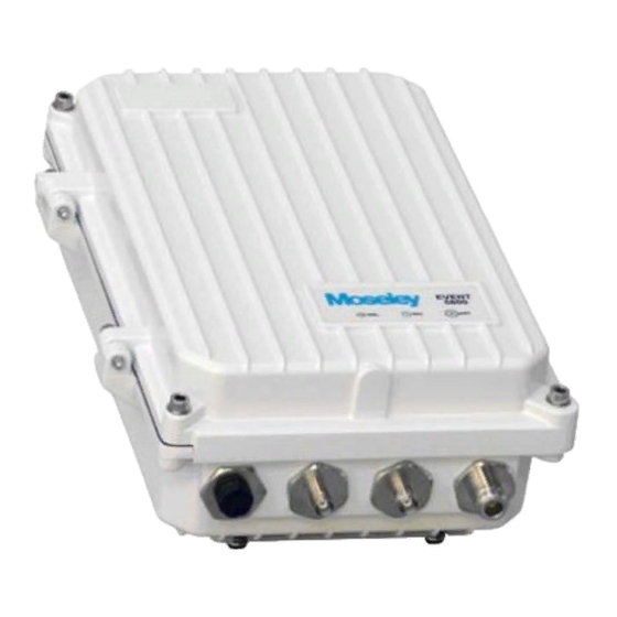
Event 5800
Moseley Event 5800 Manuals
Manuals and User Guides for Moseley Event 5800. We have
1
Moseley Event 5800 manual available for free PDF download: Installation & Reference Manual
Moseley Event 5800 Installation & Reference Manual (86 pages)
Brand:
Moseley
| Category:
Radio
| Size: 1 MB
Table of Contents
Table of Contents
5
1 Safety Precautions
11
RF Energy Health Hazard
11
Protection from Lightning
11
Protection from RF Burns
11
Risk of Personal Injury from Fiber Optics
11
This Is a Class a Product
11
Turn off All Power before Servicing
11
Power Supply Safety Requirements
12
Battery Must be Replaced Correctly
12
Proper Disposal
12
Equipment RF Protection
12
Regulatory Notices
13
2 System Description
15
Introduction
15
Example Applications
15
Operational Overview
15
Figure 2-1. Example Installation
16
Table 2-1. Key Benefits/Advantages
16
System Features
17
Physical Description
18
Back Panel
18
Hardware Modules
18
Figure 2-3. Transceiver Back Panel
18
Figure 2-4. Receiver-Only Back Panel
18
Figure 2-5. EVENT 5800 Modules
19
Table 2-2. Master I/O Modules
19
Table 2-3. Supported E1/T1 Combinations
19
Back Panel Connectors
20
Power Supply Module Connector
20
Controller Module Connectors
20
Standard Master I/O Module Connectors
21
Gige Master I/O Module Connectors
21
42Xe1/T1 Master I/O Module Connectors
21
ASI Mini I/O Module Connectors
22
Optional OC-3 Mini I/O Module Connectors
22
Optional STM-1 Mini I/O Module Connectors
22
Leds
22
Back Panel Leds
22
Figure 2-7. Back Panel Leds
22
External AC to DC Converter
24
Block Diagram & Functional Components
24
Figure 2-9. EVENT 5800 Block Diagram
24
Consecutive Point Architecture
26
Figure 2-10. Ring Configuration
27
Spanning Tree Protocol (STP)
28
1+1 Protection
28
Protected Non-Diversity (Hot Standby)
28
Figure 2-11. Consecutive Point Network
28
Protected Diversity
29
Frequency Diversity
29
Spatial Diversity
29
1+1 Multi-Hop Repeater Configuration
29
Figure 2-12. 1+1 Non-Diversity Mode Protection
29
Figure 2-13. 1+1 Diversity Mode Protection
29
Figure 2-15. 1+1 Multi-Hop Repeater Configuration
30
Figure 2-16. Back Panel Connections for Drop/Insert Capability
30
Data Interfaces
31
100 Mbps Fast Ethernet
31
Two Network Operation
31
Single Network Operation
31
Gigabit Ethernet (1000 Mbps)
31
Figure 2-17. Two Network Operation
31
Figure 2-18. Single Network Operation
31
Gige Port Based VLAN
32
Ethernet Quality of Service (Qos)
32
Figure 2-19. Gige Port Based VLAN
32
Gigabit Ethernet Link Aggregation Configuration
33
2+0 East/East Configuration
33
Figure 2-20. Ethernet Quality of Service (Qos)
33
Crosspoint Switch
34
Figure 2-22. Crosspoint Switch
34
Figure 2-23. Crosspoint Switch (A) Repeater and (B) Add/Drop Examples
34
STM-1 Specifications
35
STM-1 Mux/Demux (Optional)
35
Power Management
35
Figure 2-24. STM-1 Mux/Demux
35
Network Management
36
IP Address
36
Network
37
NMS Network Operational Principles
37
Figure 2-25. PC/EVENT 5800 on same Subnet
37
Third Party NMS Support
38
System Loopbacks
38
Figure 2-26. Dtvlinks on Different Subnets
38
3 Pre-Installation Procedures
39
Site Evaluation
39
Critical System Calculations
41
Received Signal Level (RSL) and Link Budget
41
Table 3-1. Maximum IDU/ODU Cable Lengths
41
Fade Margin Calculation
42
Availability Calculation
42
Frequency Plan Determination
43
Figure 3-1. 5.8 Ghz Frequency Plan
43
Facility Requirements
44
Antenna Planning
44
Transmit Power Setup
44
Table 3-2. Maximum Output Power Vs. Modulation Order for EVENT 5800
44
Ghz Band
45
Internal Antenna
45
External Antenna
45
Table 3-3. Maximum Power Settings for 5.3Ghz U-NII Band Operation (US)
46
4 Installation
47
Unpacking
47
Notices
47
Pre-Installation Notes
47
Back-To-Back Bench Testing
47
EVENT 5800 Installations
48
Figure 4-1. Back-To-Back Testing Configuration
48
External Waveguide Filter Installation
49
Rack Installation
49
External Equipment Connections
49
Controller Module Connectors
49
Standard Master I/O Module Connectors
50
Gige Master I/O Module Connectors
50
42Xe1/T1 Master I/O Module Connectors
50
ASI Mini I/O Module Connectors
51
Optional OC-3 Mini I/O Module Connectors
51
Optional STM-1 Mini I/O Module Connectors
51
Ground Connections
51
Antenna/Feed System
51
Antenna Mounting
51
Transmission Line
52
Environmental Seals
52
Antenna & Transmission Line Testing
52
Connect the Power Source
52
Link Alignment
53
EVENT 5800 RSL Output
53
Figure 4-5. DC Power Cable Connector
53
Figure 4-7. RSSI Output Vs. Received Signal
54
5 Quick Setup Guide
55
Quick Start Hardware Overview
55
Ensure Coaxial Connections
55
Polyphaser
55
Quick Start Software Settings
55
PC Network Configuration
55
Default IP Address
56
Default User Name/Password
56
IP Address Configuration
56
Figure 5-2. IP Address Label Location
56
Table 5-1. Default User Names & Passwords
56
Link Configuration
57
Site Attributes
58
Reset to Factory Defaults
59
Command Line Interface (CLI) Access
59
CLI Access Via NMS Ethernet
59
CLI Access Via Serial Port
59
Table 5-2. Serial Cable Pinout
59
Table 5-3. Serial Port Parameters
59
6 On-Site Service
62
Removing a Module
62
Figure 6-1. EVENT 5800 Modules
62
Figure 6-2. Thumbscrew and Corner Screw Locations
62
Installing a Module
63
Figure 6-3. Threaded Hole Locations
63
Figure 6-4. Guides for Installing Cards
63
7 Specifications
65
System Specifications
65
Ethernet Performance
66
100 Base TX Ethernet Performance
66
Table 7-1. 100 Base TX Ethernet % Nominal Throughput
67
Table 7-2. 100 Base TX Ethernet Latency (Msec)
67
Gigabit Ethernet (Gige) Performance
68
Table 7-3. Gigabit Ethernet % Nominal Throughput
68
Table 7-4. Gigabit Ethernet Latency (Msec)
68
8 Connectors
71
DC Input (Power) Connector
71
Ethernet 100Basetx Payload Connector
71
Ethernet 1000Baset Payload Connector
71
SONET Payload Connector
72
STM-1 Payload Connector
72
DVB/ASI, DS-3, E-3, STS-1 Payload Connector
72
NMS 10/100Basetx Connector 1-2
72
Alarm/Serial Port Connector
73
T1/E1 Channels 1-2 Connector
73
T1/E1 Channels 3-16 Connector
74
USB (for Future)
75
Data Order Wire
76
Rs-422
76
Rs-232
76
Appendix A. Abbreviations & Acronyms
78
Appendix B. ΜV - Dbm Conversion Chart
80
Appendix C. FCC Applications Information
82
Appendix D. Customer Service
84
Technical Consultation
84
Factory Service
84
Field Repair
85
Advertisement
Advertisement
Related Products
Moseley Expedio
Moseley NXE1-20
Moseley Categories
Transmitter
Remote Control
Radio
Receiver
Measuring Instruments
More Moseley Manuals
Login
Sign In
OR
Sign in with Facebook
Sign in with Google
Upload manual
Upload from disk
Upload from URL