Sign In
Upload
Manuals
Brands
MORLEY-IAS Manuals
Smoke Alarm
ZX1e
MORLEY-IAS ZX1e Manuals
Manuals and User Guides for MORLEY-IAS ZX1e. We have
2
MORLEY-IAS ZX1e manuals available for free PDF download: Installation Manual, User Manual
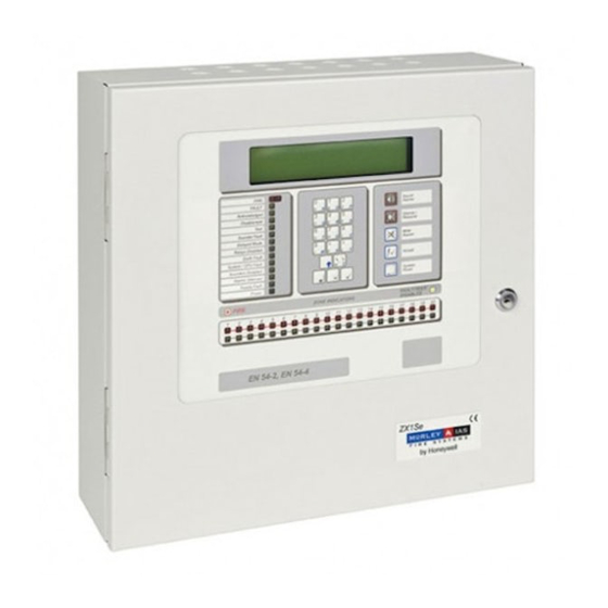
MORLEY-IAS ZX1e Installation Manual (46 pages)
Fire Alarm Control Panels
Brand:
MORLEY-IAS
| Category:
Smoke Alarm
| Size: 1 MB
Table of Contents
Table of Contents
2
1 Introduction
5
Notice
5
Warnings and Cautions
5
National Approvals
6
En54 Information
6
2 Unpacking
8
Table 1 - Packing Contents List
8
3 Installation
9
Installing the Enclosure
9
Removing the Chassis
9
Mounting the Enclosure to the Wall
9
Remounting the Chassis
9
Dimensions and Fixing Points
10
Figure 1 - Panel Fixing Centres - Zx1E / Zx2E
10
Figure 2 - Panel Fixing Centres - Zx5E
10
Identification of Parts
11
Figure 3 - Enclosure Arrangement - Zx5E
11
Figure 4 - Enclosure Arrangement - Zx1E / Zx2E
11
Base Card
12
CPU Board
12
Display / Keyboard
12
Internal Printer (ZX5E Option Only)
12
Zone Extender Card (ZX5E Option Only)
12
External Connections
13
Mains Power Input
13
Figure 5 - Mains Input Arrangement - Zx1E / Zx2E
13
ZX1E / ZX2E Arrangement
13
ZX5E Arrangement
13
Figure 6 - Mains Input Arrangement - Zx5E
14
Mains Cable Glands
14
Battery Installation
15
General Introduction
15
ZX1E / ZX2E Arrangement
15
Zx1E / Zx2E Battery Installation
15
ZX5E Arrangement
16
General Battery Connection
16
Zx5E Battery Installation
16
Detection Loops
17
Table 2 - Maximum Loop Lengths
17
Loop Wiring Installation
18
Slc Connections
18
Figure 10 - Loop Wiring Without Isolators
18
EMC Compliance
19
Figure 11 - Loop Wiring with Isolators- Prefered Alternative
19
Panel Loop Loading
19
Slc Loop - Emc Absorber Installation
19
Sounder Circuits
20
Figure 13 - Sounder Terminal Connection Points - Zx2E
20
Figure 14 - Sounder Terminal Connection Points - Zx5E
20
Figure 15 - Sounder Wiring
21
Auxiliary Relay Outputs
22
Figure 16 - Relay Output Terminal Connection Points - Zx1E / Zx2E
22
Figure 17 - Relay Output Terminal Connection Points - Zx5E
22
Auxiliary Supply Output
23
Figure 18 - Auxiliary Output Connections - Zx1E / Zx2E
23
Figure 19 - Auxiliary Output Connections - Zx5E
23
Figure 20 - Auxiliary Output - Ferrite Absorber (Typical )
23
Panel Networking / Graphics PC Interface
24
Local Panel Network
24
Master Panel to Superior Master Panel
24
Panel to Graphics PC
24
Peripheral Loop
25
Table 3 - List of Compatible Peripheral Devices
25
Daisy Chain Style Installation
26
EMC Compliance
26
Figure 21 - Typical RS485 - 'Daisy Chain' Wiring
26
Figure 22 - Typical RS485 - 'Loop' Wiring
26
Loop Style Installation
26
RS485 Wiring Arrangements
26
Rs485 Loop - Emc Absorber Installation
26
Cable Screen - Earth Connections
27
High Integrity Loop
27
Group Disable Input
27
Class Change Input
27
Rs485 Screen - Earth Arrangement
27
Recommended Cables
28
Base Card Power Supply Connections
28
Figure 25 - Base Card Power Connections
28
Cable Routing
29
Figure 26 - Recommended Cable Routing Arrangement - Zx1E / Zx2E
29
Figure 27 - Recommended Cable Routing Arrangement - Zx5E
29
Installing Additional Equipment
30
Figure 28 - Positions for Additional Boards - Zx2E
30
General Introduction
30
ZX1E Arrangement
30
Figure 29 - Positions for Additional Boards - Zx2E
31
Figure 30 - Positions for Additional Boards - Zx5E
31
ZX2E Arrangement
31
ZX5E Arrangement
31
Figure 31 - Mounting the Loop Driver
32
Loop Driver Cards
32
Table 4 - Jumper Setting for Loop Voltage
32
Voltage Selection
32
ZX1E / ZX2E Jumper Settings
32
485 / 232 Interface Cards
33
Table 5 - Jumper Setting for Loop Voltage
33
ZX5E Jumper Settings
33
Mounting the Card above the Loop Driver Module
34
Mounting the Card Directly to the Base Card
34
Printer Module (ZX5E Only)
35
4 Standby Battery Calculations
36
Table 6 - Current Rating Chart - Zx1E / Zx2E
36
Alarm Condition
37
Table 7 - Current Rating Chart - Zx5E
37
Local Systems Ampere Hour Calculation
38
Sensor Current Calculations
38
Adjustment Factors
38
Alarm Load
38
Quiescent Load
38
5 Maintenance
39
Maintenance Schedule
39
Daily Attention
39
Monthly Attention
39
Quarterly Attention
39
Yearly Attention
39
Replacement of Components
40
Lithium Standby Battery
40
Liquid Crystal Alphanumeric Display
40
Standby Batteries
40
6 Specifications
41
Functional Specifications
41
Zx1E / Zx2E Functional Specifications
41
Zx5E Functional Specifications
42
Power Supply and Charger
43
Zx1E / Zx2E Power Supply and Charger Specifications
43
Zx5E Power Supply and Charger Specifications
44
Advertisement
MORLEY-IAS ZX1e User Manual (28 pages)
Brand:
MORLEY-IAS
| Category:
Control Panel
| Size: 1 MB
Table of Contents
Table of Contents
2
1 Introduction
4
Notice
4
Warnings and Cautions
4
National Approvals
4
2 User Control Levels
5
Level Definition
5
User Passwords
5
3 Controls and Displays
6
Control Keys
6
Zx1E, Zx2E Controls and Displays
6
Zx5E Controls and Displays
6
Table of Tables TABLE 1 - CONTROL KEY FUNCTIONS
6
Figure 3 - System Control Led Display
7
Front Panel Led Indications
7
Table 2 - Alphanumeric and Interactive Control Keys
7
Able 3 - Led Functions
8
Alphanumeric Display Indications
9
Display Examples - Faults
9
Display Examples - Fire Alarms
9
Normal Condition
9
4 Level 1 Display / Control Functions
10
Normal Conditions
10
Ac Mains Power Fail Conditions
10
Fire
10
Conditions
10
Override Delays
10
Fault Conditions
10
5 Level 2 Control Functions
11
Power Failure Condition
11
AC Mains Power Failure Indication
11
Battery Low / Charger Failure
11
Fault Conditions
12
Fault Indication
12
User Actions
12
Fire Alarm Conditions
12
Fire Alarm Indications
12
User Option Functions
13
Table 4 - User Menu Options
13
Test
14
Configuring the Test
14
LCD Test
14
LED Test
14
Zones Test
14
Terminating the Test
15
Inspecting Other Conditions During a Walk Test
16
Output Test
16
Audible Indicator Test
17
Enable / Disable Functions
17
Enable or Disable Inputs
18
Enable or Disable Zones
18
Enable or Disable Keys
19
Configure Day Mode Delay Period / Disable Operation
20
Enable or Disable Delayed Day Modes
20
Manual Override
20
Enable or Disable Delays
21
Enable or Disable Outputs
21
Time
17
Print
22
Table 5 - View Mode Options
23
View
23
7 Level 3 Programmer Functions
24
6 Delayed Day Mode Operation
24
8 Log Book
25
Table 6 - Logbook Reference Data
25
Table 7 - Logbook Event Data
26
Advertisement
Related Products
MORLEY-IAS ZX2e
MORLEY-IAS ZX5e
MORLEY-IAS ZX1Se
MORLEY-IAS ZX2Se
MORLEY-IAS ZX5Se
MORLEY-IAS ZX10Se
MORLEY-IAS ZXa
MORLEY-IAS ZXe
MORLEY-IAS ZXr-A
MORLEY-IAS ZXr-P
MORLEY-IAS Categories
Control Panel
Fire Alarms
Marine Equipment
Repeater
Smoke Alarm
More MORLEY-IAS Manuals
Login
Sign In
OR
Sign in with Facebook
Sign in with Google
Upload manual
Upload from disk
Upload from URL