Sign In
Upload
Manuals
Brands
Moog Manuals
Control Unit
D668 Series
Moog D668 Series Manuals
Manuals and User Guides for Moog D668 Series. We have
2
Moog D668 Series manuals available for free PDF download: User Manual
Moog D668 Series User Manual (109 pages)
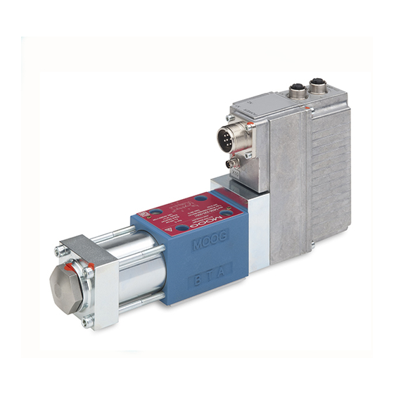
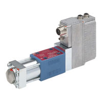
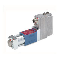
SERVOMOTOR-DRIVEN PROPORTINAL VALVE
Brand:
Moog
| Category:
Control Unit
| Size: 2 MB
Table of Contents
Table of Contents
3
1 General Information
7
Notes on User Manual
7
Subject to Change Without Notice and Validity
7
Completeness
7
Storage Location
8
Typographical Conventions
8
Structure of the Warning Notes
9
Supplemental Documents
9
Intended Operation
10
Selection and Qualification of Personnel
11
Structural Modifications
12
Environmental Protection
13
Acoustic Emissions
13
Disposal
13
Responsibilities
14
Warranty and Liability
15
Registered Marks and Trademarks
16
2 Safety
17
Handling in Accordance with Safety Requirements
17
Occupational Safety and Health
18
General Safety Instructions
20
Electrical Hazards
20
Esd
20
Installation and Operation in Safety Oriented Systems
21
Specific Phases of Operation
21
Mounting
21
Start-Up
21
Maintenance and Repairs
21
Pressure Limitation
22
3 Product Description
23
Function and Mode of Operation
23
Representative Depiction of the Valve
24
Servomotor
25
Liquid Cooling
26
Coolant Specification
26
Lubrication of the Rotary-Linear Converter
28
Internal Lubrication Via T-Port
28
External Lubrication Via X-Port
28
MSD Servo Drive
29
Signal Interfaces
29
Power Connector
29
Signal Connector
29
Safety Function / Fail-Safe
30
Fail-Safe Identification
30
Restarting the Valve
31
Hydraulics
32
Spool Position Control
32
Valve Configurations and Hydraulic Symbols
33
4-Way and 3-Way Operation
33
Leakage Port y
33
Electrical and Hydraulic Zero Positions
34
Control
35
Signal Types for Set-Point and Actual Value
35
Signal Type Identification
35
Spool Position Control Command Inputs on MSD Servo Drive
36
Analog Actual Value Output on MSD Servo Drive
37
Digital In- and Outputs on MSD Servo Drive
37
Configuration Software
38
Moog DRIVE ADMINISTRATOR Software
38
Nameplate
39
4 Characteristic Curves
40
Flow Diagram (4-Way Operation)
40
Flow Signal Characteristic Curve
41
5 Transportation and Storage
42
Checking / Unpacking a Delivery
44
Scope of Delivery of the Valve
44
Storage
44
6 Mounting and Connection to the Hydraulic System
45
Dimensions (Installation Drawing)
46
Mounting Surface
46
Surface Quality
46
Holes in Mounting Surface
46
Mounting the Valve
46
Tools and Materials Required
46
Specification for Installation Screws for the Valves
47
Procedure
47
7 Electrical Connection
49
Safety Instructions for Installation and Maintenance
49
Protective Grounding and Electrical Shielding
51
Moog DRIVE ADMINISTRATOR
51
Block Diagram
52
Arrangement of Connectors
52
Power Connector
53
Pin Assignment of Power Connector
53
Mating Connector for Power Connector
53
Permissible Motor Cable Lengths
53
Signal Connector
54
Pin Assignment of Signal Connector
54
Mating Connector for Signal Connector
54
General Notes on Wiring
55
Cable Routing
55
Tools and Materials Required
55
Procedure
56
Protective Grounding, Equipotential Bonding and Shielding
56
Overview
56
Equipotential Bonding and Protective Grounding
57
General Principles
58
Electrical Shielding
59
Cables
59
Connecting the Shield
59
Electromagnetic Compatibility (EMC)
60
Communication Via the Moog DRIVE ADMINISTRATOR
61
8 Start up
62
Preparations
64
Start-Up of the Valves
65
Configuration of the Valves / MSD Servo Drives
66
Factory Setting of the Valves / MSD Servo Drives
66
Device Commissioning File
67
Download of the Device Commissioning File from the Internet
67
Upload of the Device Commissioning File to the MSD Servo Drive
68
Adapting / Storing of the Parameters
69
Filling and Flushing the Hydraulic System
70
Start-Up of the Hydraulic System
71
Venting the Actuator
71
9 Operation
72
Preparations for Operation
74
Operation of the Valve
74
Shutting down the Valve
75
10 Service
77
Removing the Valves
79
Tools and Materials Required
79
Removing
80
Maintenance
80
Checking and Replacing the Port O-Rings
81
Tools and Materials Required
81
Checking and Replacing the O-Rings
81
Troubleshooting
81
Leaks
82
Leak at the Valve Connecting Surface
82
Leak at the Sinter Metal Filter of the Servomotor
82
No Hydraulic Response by the Valve
82
Instability of the External Control Loop
83
Instability of the Internal Valve Control Loops
84
Spool Position Control
84
Repair
84
11 Technical Data
86
Nameplates
87
Model Number and Type Designation
89
Data Matrix Code
93
Electromagnetic Compatibility (EMC)
93
Technical Data D668 - ISO 4401-07 / NG16
94
Mounting Surface
94
Mounting Pattern of Mounting Surface
94
Data D668 - ISO 4401-07 / NG16
95
Dimensions (Installation Drawing)
97
Valve Configurations and Hydraulic Symbols
98
Characteristic Curves
99
12 Accessories, Spare Parts and Tools
101
Accessories for D668 Series Valves
101
13 Ordering Information
103
14 Appendix
104
Abbreviations, Symbols and Identification Letters
104
Additional Literature
105
Fundamentals of Hydraulics
105
Moog Publications
105
Quoted Standards
106
Din
106
Iso
107
Iec
108
Iso
108
Quoted Directives
108
Advertisement
Moog D668 Series User Manual (17 pages)
Servomotor-Driven Proportional Valves
Brand:
Moog
| Category:
Control Unit
| Size: 0 MB
Table of Contents
Installation
3
Installazione
12
Manutenzione
13
Montaje
15
Eliminación de Residuos
16
Advertisement
Related Products
Moog D661-***S series
Moog D661-***G series
Moog D661-***H series
Moog D663 series
Moog D661 series
Moog D665 series
Moog D664 series
Moog D661K 3 Series
Moog D662K D 3 Series
Moog D664K L 8 Series
Moog Categories
Synthesizer
Control Unit
Servo Drives
Medical Equipment
Security Camera
More Moog Manuals
Login
Sign In
OR
Sign in with Facebook
Sign in with Google
Upload manual
Upload from disk
Upload from URL