Sign In
Upload
Manuals
Brands
Monarch Manuals
Controller
NICE7000
Monarch NICE7000 Manuals
Manuals and User Guides for Monarch NICE7000. We have
1
Monarch NICE7000 manual available for free PDF download: User Manual
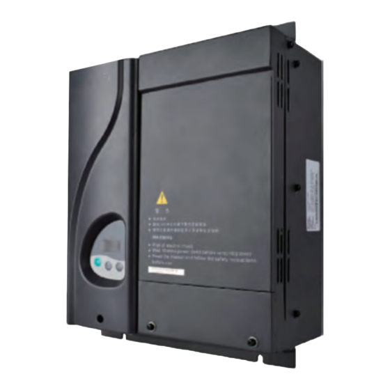
Monarch NICE7000 User Manual (238 pages)
Intergrated Elevator Controller
Brand:
Monarch
| Category:
Controller
| Size: 10 MB
Table of Contents
Preface
2
Easier Use
4
Introduction
4
Product Features
4
Product Overview
4
Function List of the NICE7000
5
More Friendly Operation
5
Table of Contents
12
Chapter 1 Safety Information and Precautions
16
Safety Precautions
17
General Precautions
19
Requirement on the Residual Current Device (RCD
19
Motor Insulation Test
20
Thermal Protection of Motor
20
Motor Heat and Noise
20
Switch (Contactor) on the Input and Output Sides of the Controller
21
Use Outside the Rated Voltage
21
Surge Suppressor
21
Altitude and De-Rating
21
Adaptable Motor
22
Precautions on Selecting Residual-Current Circuit Breaker (RCCB)
22
Chapter 2 Product Information
24
System Configuration of the NICE7000
25
System Components of the NICE7000
25
Designation Rules and Model Description
26
System Structure of the NICE7000
26
NICE7000 Structures
27
Models
27
Technical Specifications
29
Physical Appearance and Mounting Dimensions
31
Mounting Dimensions of the NICE7000
31
Optional Parts
32
Selection of Adaptable Motor
33
Chapter 3 Mechanical and Electrical Installation
34
Installation Environment Requirements
35
Installation Clearance Requirements
35
Clearance Around the NICE7000 for Installation
35
Mechanical Installation
35
Diagram of Mounting Holes
36
Electrical Installation
37
Terminal Arrangement of the NICE7000
37
Main Circuit Wiring
37
Description of Main Circuit Terminals
38
Description of Control Circuit Terminals
39
Description of Indicators on the MCB
40
CTB Board (MCTC-CTB)
40
Appearance, Structure and Installation Method of the CTB
41
Wiring of CTB Terminals
41
Wiring Description of CTB Terminals
41
Vertical Installation
41
Display Board (MCTC-HCB)
43
MCTC-HCB-H (Dot-Matrix Display Board)
44
Common HCB Types
44
Appearance, Dimensions, and Installation Method of HCB-H
44
Input and Output Terminals of HCB-H
45
MCTC-HCB-R1 (Ultrathin Dot-Matrix Display Board)
46
Input and Output Terminals of HCB-R1
46
MCTC-HCB-D2 (Ultrathin Segment LCD Display Board)
47
Input and Output Terminals of HCB-D2
47
MCTC-HCB-D5 (Ultrathin Segment LCD Display Board)
48
Input and Output Terminals of HCB-D5
49
MCTC-HCB-U1 (4.3-Inch Segment LCD Display Board)
50
Appearance, Dimensions, and Installation Method of HCB-U1
50
Input and Output Terminals of HCB-U1
50
MCTC-HCB-V1 (6.4-Inch Segment LCD Display Board)
51
Appearance, Dimensions, and Installation Method of HCB-V1
51
Input and Output Terminals of HCB-V1
51
MCTC-HCB-B (no Display Hall Call Board)
52
Appearance, Dimensions, and Installation Method of HCB-B
52
Input and Output Terminals of HCB-B
53
Relay Output and Pin Definition of CN2
54
Floor Address Setting by S1
54
S2 Description
54
Function Setting of the HCB-B
54
CCB Board (MCTC-CCB)
55
Appearance, Dimensions, and Installation Method of the CCB
55
Input and Output Terminals of the CCB
56
Selection and Use of the MCTC-PG Card
57
Appearance of the MCTC-PG Card and Its Installation on the Controller
57
Selection of the MCTC-PG Card
57
Terminal Wiring and Description of the MCTC-PG Card
58
Wiring between MCTC-PG-E and the Controller
58
Definitions of the CN1 Terminals of Different MCTC-PG Card Models
59
Selection of Braking Components
60
Precautions on Connecting the MCTC-PG Card
60
Brakingresistor Selection for the NICE7000 Models
60
Selection of Peripheral Electrical Devices
62
Connection to Peripheral Electrical Devices
62
Description of Peripheral Electrical Devices
63
Electrical Wiring Diagram of the NICE7000 Control System
64
Installation of Shaft Position Signals
64
Arrangement of Shaft Position Signals
65
Installation of Leveling Signals
66
Installation Requirements of Leveling Switches
66
Installation of Slow-Down Switches
67
Slow-Down Distances Based on Different Rated Elevator Speeds
68
Installation of Limit Switches
68
Installation of Final Limit Switches
69
Chapter 4 Use of the Commissioning Tools
71
Use of the Onboard Keypad
72
Appearance of the Keypad
72
Setting the Called Floor
73
F0: Display of Floor and Running Direction
73
F1: Command Input of the Running Floor
73
F2: Fault Reset and Fault Code Display
74
F3: Time Display
74
F4: Contract Number Display
74
F6: Door Open/Close Control
74
FA: Auto-Tuning
75
Use of the LED Operation Panel
75
Connection between the Operation Panel and the NICE7000
75
Diagram of the LED Operation Panel
76
Description of Indicators
76
Status Indicators
76
Unit Indicators
76
Description of Keys on the Operation Panel
77
Operation Procedure
77
Operation Procedure on the Operation Panel
78
Shift between the Three Levels of Menus
78
Chapter 5 System Commissioning and Functions
79
Check before Commissioning
80
Commissioning Procedure of the System
80
Check the Field Mechanical and Electric Wiring
81
Check the Encoder
81
Check the Power Supply before Power-On
81
Trial Running
82
Check the Grounding
82
Motor Auto-Tuning Process
82
Door Machine Controller Commissioning
84
In the Terminal Control Mode of the Door Machine Controller
84
NO/NC State of the Door Input Signals
85
Riding Comfort
85
Controller Output
86
Mechanical Construction
88
Password Setting
89
Example of Changing the Password
89
System Functions
90
Emergency Evacuation at Power Failure
90
Eps
90
220 V UPS Circuit
90
Various Contacts of the Contactors
91
Recommended UPS Power for each Power Class
91
Parameter Setting under the 220 V UPS Scheme
91
48 V EPS Principle Diagram
92
48 V EPS Circuit
92
Shorting PMSM Stator
92
Wiring When Using the Special Contactor
93
Independent Contactor + Relay NC Contact
93
Parallel/Group Control
94
Wiring of the Independent Contactor + Relay NC Contact
94
Parameter Setting under the Shorting PMSM Stator Scheme
94
Parameter Setting of Parallel/Group Control
94
Parallel Control
95
Parameter Setting
95
Address Setting of Physical Floors
95
Parameter Setting Example of Parallel Control
96
Wiring for Parallel Control by CAN2
97
Wiring When CAN2 (CN6) Is Used for Parallel Control
97
Group Control
97
Parameter Setting of Group Control
97
Opposite Door Control
98
Parameter Setting Example of Group Control on Three Elevators
98
Wiring When CAN2 (CN6) Is Used for Group Control
98
Opposite Door Control Modes and Parameter Setting
99
HCB Wiring of Opposite Door Control
100
Chapter 6 Function Code Table
103
Function Code Description
104
Function Code Groups
104
Chapter 6 Function Code Table
104
Function Code Table
105
Chapter 7 Description of Function Codes
135
Group F0: Basic Parameters
136
Influences of Carrier Frequency Adjustment
138
Group F1: Motor Parameters
138
Group F2: Vector Control Parameters
140
Relationship between Running Frequencies and PI Parameters
141
Group F3: Running Control Parameters
143
Group F4: Floor Parameters
147
Running Time Sequence
147
Group F5: Terminal Function Parameters
149
Fire Emergency Signal
151
Overload Signal
151
Full-Load Signal
151
Shorting Door Lock Circuit Contactor Feedback
152
Firefighter Switch Signal
152
EPS Valid Signal
152
Elevator Lock Signal
152
Fire Emergency Floor Switchover
153
Parking Floor Switchover
153
Down Collective Selective Switch
153
Peak Service
153
Fire Emergency Floor Arrival Signal Feedback
154
Brake and RUN Contactors Healthy
154
Fault State
154
Running Monitor
154
Group F6: Elevator Logic Parameters
155
Emergency Evacuation Automatic Switchover
155
Controller Healthy
155
Emergency Buzzer Control
155
F6-05 Is Enabled through Bit Addressing
156
Converting Binary Value of F6-05 to Decimal
157
Convert the Binary Value to Decimal
157
Group F7: Intelligent Commissioning Parameters
170
Group F8: Auxiliary Logic Parameters
172
Group F9: Time Parameters
176
Group FA: Auxiliary Parameters
177
Group Fb: Door Function Parameters
182
Group FC: Brief Fault Information
185
Group Fd: Parallel/Group Control Parameters
186
Group FE: Display Parameters
187
Group FF: Factory Parameters
188
Group FH: Close-Loop Parameters
188
Group FL: Extension Terminal Function Parameters
190
Group Fr: Leveling Adjustment Parameters
192
Viewing the Leveling Adjustment Record
193
Group FU: Monitoring Parameters
194
Elevator State Display
194
LED Display of the Elevator State
195
Example of Input State Display
197
Viewing Mod1 Communication State between Hcbs and MCB
201
Group FP: User Parameters
202
Groups E: Fault Details
203
Troubleshooting
205
Routine Maintenance
206
Periodic Inspection
206
Chapter 8 Maintenance and Troubleshooting
206
Replacement of Vulnerable Components
207
Storage of the Controller
207
Description of Fault Levels
207
Service Life of Cooling Fan and Filter Electrolytic Capacitor
207
Fault Levels
208
Fault Information and Troubleshooting
209
Emc
225
Definition of Terms
226
First Environment
226
Second Environment
226
Category C1 Controller
226
Chapter 9 EMC
226
Introduction to EMC Standard
226
Requirements on Satisfying the EMC Directive
227
Selection of Peripheral EMC Devices
227
Installation of EMC Input Filter on Power Input Side
227
Recommended Manufacturers and Models of EMC Filter
228
Installation of AC Input Reactor on Power Input Side
229
Recommended Manufacturers and Models of AC Input Reactors
229
Shielded Cable
230
Requirements for the Shielded Cable
230
Installation Precautions of the Shielded Cable
231
Grounding of the Shielded Cable
231
Cabling Requirement
231
Solutions to Common EMC Interference Problems
232
Cabling Diagram
232
Advertisement
Advertisement
Related Products
Monarch nice3000
Monarch NICE1000
Monarch NICE 5000
Monarch Nova-Strobe bax
Monarch Nova-Strobe bax/et
Monarch Nova-Strobe dax
Monarch Nova-Strobe vbx
Monarch NeuroSigma
Monarch NG1020
Monarch Nova-Strobe DBL
Monarch Categories
Indoor Furnishing
Printer
Transmitter
Measuring Instruments
Label Maker
More Monarch Manuals
Login
Sign In
OR
Sign in with Facebook
Sign in with Google
Upload manual
Upload from disk
Upload from URL