Sign In
Upload
Manuals
Brands
MKS Manuals
Transducer
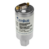
Baratron 750C
MKS Baratron 750C Manuals
Manuals and User Guides for MKS Baratron 750C. We have
1
MKS Baratron 750C manual available for free PDF download: Manual
MKS Baratron 750C Manual (84 pages)
Pressure Transducers And Relay Systems
Brand:
MKS
| Category:
Transducer
| Size: 0 MB
Table of Contents
German
3
Table of Contents
3
Pressure Transducer Safety Information
11
Symbols Used in this Instruction Manual
11
Symbols Found on the Unit
12
Table 1: Definition of Symbols Found on the Unit
12
Safety Procedures and Precautions
13
Sicherheitshinweise für den Druckmeßumformer
15
In dieser Betriebsanleitung Vorkommende Symbole
15
Erklärung der am Gerät Angebrachten Symbole
16
Tabelle 2: Bedeutung der am Gerät Angebrachten Symbole
16
Sicherheitsvorschriften und Vorsichtsmaßnahmen
17
French
19
Informations Relatives À la Sécurité Pour Le Transducteur de Pression
19
Symboles Utilisés Dans Ce Manuel D'utilisation
19
Symboles Apparaissant Sur L'unité
20
Mesures de Sécurité Et Précautions
21
Medidas de Seguridad del Transductor de Presión
23
Símbolos Usados en Este Manual de Instrucciones
23
Símbolos Hallados en la Unidad
24
Procedimientos y Precauciones de Seguridad
25
Chapter One: General Information
27
Introduction
27
Table 5: the 7Xxc Series Model Selection Guide
27
How this Manual Is Organized
28
Customer Support
29
Chapter Two: Installation
31
How to Unpack the 7Xxc Series Unit
31
Unpacking Checklist
31
Table 6: Interface Cables
31
Product Location and Requirements
32
Interface Cables
33
Generic Shielded Cable Description
34
Figure 1: Preferred Method
35
Figure 2: Alternate Method to Use When Cable Clamp Is Not Available
35
Setup
36
Mounting the Unit
36
Figure 3: Acceptable Vertical Mounting Positions
36
Figure 4: Unacceptable Vertical Mounting Positions (Units < 20 Psi Full Scale)
37
Figure 5: Acceptable Horizontal Mounting Positions
37
Fittings
38
Table 7: Fittings Available
38
English
39
Making Welded Connections
39
Making Mechanical Connections
39
Electrical Information for a Current Unit
40
Figure 6: Line Resistance Equation
40
Figure 7: Total Resistance in Line
40
Figure 8: Electrical Scheme for the 4 to 20 Ma Unit
41
Electrical Information for a Voltage Unit
42
Figure 9: Electrical Scheme for a Voltage Unit
42
Connectors
43
Table 8: 9-Pin Type "D" Connector Pinout
44
Table 9: 15-Pin High Density Type "D" Connector Pinout
44
Table 10: Bendix 4 Position PTO Connector Option 1 Pinout
45
Table 11: Bendix 4 Position PTO Connector Option 2 Pinout
45
Table 12: Flying Leads (Model Code F) Pinout
46
Table 13: Flying Leads (Model Code L) Pinout
46
Dimensions
47
Single Ended Version
47
Figure 10: Dimensional Drawing of the Single-Ended Design
47
Table 14: Dimensions for Connectors and Fittings for Single-Ended Units
47
Flow-Through Version
48
Figure 11: Dimensional Drawing of the Flow-Through Design
48
Table 15: Dimensions for Connectors and Fittings for Flow-Through Units
48
How to Connect to a Type PDR Series Readout
49
Type "D" Connector (Either 9-Pin or 15-Pin High Density)
49
Table 16: Connections between PDR Readout and a Transducer (Type "D" Connector)
49
Bendix Connector (Option 1 Pinout)
50
Table 17: Connections between a PDR Readout and a Transducer (Bendix Connector)
50
How to Check the Transducer Zero
51
Figure 12: Top Cover
51
How to Zero an Absolute Transducer
52
How to Zero a Gage Unit
53
Table 18: Highest Pressure for Proper Zero Adjustment
53
Span Adjustment
54
Table 19: Output of a Compound Gage Unit at 0 Psig
54
Chapter Three: Overview
56
General
56
Sensor
56
Signal Conditioning Electronics
57
Chapter Four: Operation
59
General
59
Lowest Suggested Pressure Available for Reading
59
Lowest Suggested Pressure to Use for Control
59
Table 20: Suggested Pressures for Reading and Control
59
Chapter Five: Type R7Xxc Relay System
61
General Information
61
Initial Settings
61
Table 21: Initial Settings for the Relay System
61
Trip Point Parameters
62
Figure 13: Location of the Trip Point Adjustment Pots
62
Figure 14: Trip Point Direction Set Low
63
Figure 15: Trip Point Direction Set High
63
Setup
64
Cabling
64
Dimensions
65
Figure 16: Dimensions of the Relay Module
65
Figure 17: Top View of the Type R7Xxc Unit
66
Figure 18: Side View of the Type R7Xxc Unit
66
Mounting Instructions
67
Figure 19: Location of the Trip Point Adjustments
67
Figure 20: Screws on the Top of the Transducer
68
Electrical Information
69
Connector
69
Electrical Requirements
69
Table 22: Type R7Xxc Connector Pinout
69
Contact Rating
70
How to Configure the Trip Points
70
Figure 21: Relay Module PC Board
71
Chapter Six: Maintenance and Troubleshooting
73
General
73
Zero Adjustment
73
Troubleshooting
74
Table 23: Troubleshooting Chart
74
Appendix A: Product Specifications
75
700 Series Specifications
75
General Description
77
Product Type
77
Full Scale Range and Engineering Units
78
Table 24: Full Scale Range Ordering Code
78
Table 25: Engineering Units Ordering Code
78
Fittings
79
Table 26: Examples of Full Scale and Engineering Unit Ordering Codes
79
Table 27: Ordering Code for Fittings
79
Input/Output Settings
80
Accuracy
80
Table 28: Input/Output Selection Ordering Code
80
Table 29: Accuracy Ordering Code
80
Connector
81
Table 30: Connector Ordering Code
81
Index
83
Advertisement
Advertisement
Related Products
MKS Baratron 722A
MKS Baratron 722B
MKS Baratron 740C
MKS Baratron 742C
MKS Baratron 752C
MKS Baratron 722C
MKS Baratron 727
MKS Baratron 728A
MKS Baratron 631D
MKS Baratron 127A
MKS Categories
Controller
Measuring Instruments
Transducer
Control Unit
Industrial Equipment
More MKS Manuals
Login
Sign In
OR
Sign in with Facebook
Sign in with Google
Upload manual
Upload from disk
Upload from URL