Sign In
Upload
Manuals
Brands
Mitsubishi Heavy Industries Manuals
Air Conditioner
FDKNA SERIES
Mitsubishi Heavy Industries FDKNA SERIES Manuals
Manuals and User Guides for Mitsubishi Heavy Industries FDKNA SERIES. We have
2
Mitsubishi Heavy Industries FDKNA SERIES manuals available for free PDF download: Technical Manual
Mitsubishi Heavy Industries FDKNA SERIES Technical Manual (328 pages)
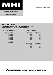
packaged/MULTI-TYPE (V-MULTI)PACKAGED AIR-CONDITIONER
Brand:
Mitsubishi Heavy Industries
| Category:
Air Conditioner
| Size: 8 MB
Table of Contents
High Static Pressure Duct Type
1
Wall Mounted Type
1
Table of Contents
3
How to Read the Model Name
5
General Information
5
Specifi C Features
5
Selection Data
6
Specifications
6
Ceiling Recessed Compact Type (FDTC)
6
Ceiling Recessed Type (FDT)
13
Ceiling Suspended Type (FDEN)
37
Satellite Ducted Type (FDUM)
59
High Static Pressure Duct Type (FDU)
79
Wall Mounted Type (FDKN)
81
Range of Usage & Limitations
91
Height and Length Restrictions for Refrigerant Piping
92
Exterior Dimensions
94
Indoor Unit
94
Wired Remote Controller
106
Precaution in Extending the Remote Control Cord
106
Remote Controller Mounting Dimensions
106
Remote Controller (Optional Parts)
106
Wireless Remote Controller
107
Outdoor Unit Dimensions
108
Inside View
114
Exterior Appearance
117
Piping System
120
Preset Point of the Protective Devices
126
Selection Chart
127
Capacity Compensation Coeffcient
128
Power Consumption Correction Factor
131
Sensible Heat Factor
134
Piping Length Limitations
137
How to Obtain the Cooling and Heating Capacity
137
Characteristics of Fan
138
Noise Level
141
Indoor Unit
141
Outdoor Unit
144
Electrical Data
145
Electrical Wiring
145
Indoor Unit
145
Outdoor Unit
152
Outline of Operation Control by Microcomputer
157
Remote Controller View
157
Operation Section
158
Automatic Operation
159
Control Parts Operation During Cooling and Heating
159
Operation Control Function by the Indoor Controller
159
Room Temperature Control (Differential of Thermostat)
159
Dehumidifying Operation ("Thermal Dry")
160
Timer Operation
160
FM Control with the Heating Thermostat Turned off
161
Hot Start (Cold Draft Prevention During Heating)
161
Auto Swing Control (Except the FDU, FDUM Model)
162
Filter Sign
162
Louver Control/Auto Louver Horizontal Set During Heating
162
Room Temperature Sensing Temperature Compensation During Heating
162
Air Flow Mode Control
163
Compressor Inching Prevention Control/Heating Overload Protection
163
Condensate Pump Motor (DM) Control [FDT and FDUM Models Only]
163
Frost Prevention During Cooling, Dehumidification
163
External Control (Remote Display) /Control of Input Signal
164
Using 1 Remote Controller to Control Multiple Units
164
Operation Control Function by the Wired Remote Controller
166
Power Failure Compensation Function
166
Remote Controller Operation Mode Switch Switching Sequence
166
Remote Controller PCB Parts Arrangement
166
Compressor Soft Start Control
167
Models FDCVA151 ~ 251
167
Operation Control Function by the Outdoor Controller
167
Compressor Protective Control According to Operating Speed
168
Compressor Protective Start III
168
Outdoor Fan Control
168
Outdoor Unit Fan Speed Control
169
Snow Protection Fan Control
169
Compressor Protective Control
170
Defrosting
170
Discharge Pipe Temperature Control
170
Anomalous Discharge Pipe Temperature
171
Anomalous Stop Due to Starting of the Compressor
172
Insufficient Refrigerant Protection Control
172
Inverter Protection Control
172
Temperature Thermistor Disconnection
172
Compressor Start Control
173
Deciding the Compressor Speed
173
Low Voltage Protection Control
173
Models FDCVA302 ~ 1002
173
Test Operation
173
Contents of Fan Speed Control
175
Outdoor Unit Fan Control
175
Fan Speed Control When the Unit Started
176
Open Phase Protection
182
Temperature Thermistor and Low Pressure Sensor Disconnection
182
Silent Mode Control
183
Abnormal Stop by Failing in Starting the Compressor
184
Compressor Rotor Lock Error
184
Pump down Control
184
Safety Precautions
185
Application Data
185
Installation of Indoor Unit
186
Ceiling Recessed Compact Type (FDTC)
186
Suspension
187
Drain Piping
187
When Embedded into Ceiling
187
Drainage Test
188
Forced Drain Pump Operation
188
Panel Installation
189
Ceiling Recessed Type (FDT)
191
Removing the Air Return Grille
195
Removing the Corner Panel
195
If the Vertical Air-Flow Direction Is Fixed
196
Corner Panel Installation
197
Ceiling Suspended Type (FDEN)
197
Wireless Remote Control Unit Operation Distance
198
Installation Preparation
198
Remove the Suspension Lug
199
Suspension Bolt Position
199
Fasten the Suspension Lugs to the Suspension Bolts
199
Attach the Unit to the Suspension Lugs
199
In Order to Make It Easier for Water to Drain out
200
Refrigerant Piping
200
Wall Mounted Type (FDKN)
201
Attaching of Mounting Plate
202
Procedure for Making Hole on the Wall
202
Forming of Piping and Drain Hose
202
Relation between Illumination at Receiver Unit and Operating Distance
202
Satellite Ducted Type (FDUM)
204
Adjusting the Unit’s Levelness
205
Blower Fan Tap Switch
205
Supply Air Duct
205
Access Door
205
Return Air Port
206
Return Air Port with Canvas Duct
207
Connection of Intake and Exhaust Ducts
207
Duct Connection
207
Drainage from the Lower Drain Socket
209
High Static Pressure Duct Type (FDU)
210
Simplified Method for Determination of Duct Dimensions
212
Installation of Wired Remote Controller
214
Installation of Outdoor Unit
215
Haulage and Installation
215
Decision of Piping Specification
217
Refrigerant Piping Work
217
Points for Attention in Installing Refrigerant Piping
220
How to Remove the Side Cover
221
Refrigerant Pipe Connection
221
Method for Connecting the Accessory Pipe
221
Air Tightness Test and Air Purge
223
Refrigerant Charge
224
Charging Refrigerant
225
Drain Piping Work
225
Electrical Wiring
225
Power Cable, Indoor-Outdoor Connecting Wires
226
Remote Controller Wiring and Connection Procedure
227
Setting Functions Using the Wired Remote Controller
228
Function Setting Method
230
Changing the Remote Control Set Temperature Range
232
Checking Operation Data
233
Test Run from an Outdoor Unit
234
Failure Diagnosis in a Test Run
235
The State of the Electronic Expansion Valve
236
Test Run from an Wired Remote Controller
236
Maintenance Data
237
Servicing
237
Evacuation Procedure
237
Trouble Shooting for Refrigerant Circuit
238
Diagnosing of Microcomputer Circuit
239
Selfdiagnosis Function
239
Display Sequence of Error, Inspection Display Lamp
241
Procedures of Trouble Diagnosis
242
Error Diagnosis Procedures at the Indoor Unit Side
242
Parts Layout on the Indoor Unit PCB
243
Check Method When the Error Code Is Display
248
Error Display "Wait"
250
Indoor – Outdoor Communications Trouble Initial
250
Indication Example in Case of Wrong Interconnection
252
Behavior When Address Setting Is Wrong
252
Communication Error between the Remote Controller and the Indoor Unit
253
Defective Indoor Unit Heat Exchanger Thermistor
254
Detective Return Air Thermistor
254
Heating Overload
255
Drain Trouble
255
Control of 1 Remote Controller VS Multiple Units
256
Excessive Number of Units (more than 17 Units)
256
Communications Are Faulty between Master and Slave Indoor Units
256
Fan Motor Abnormalities
257
Defective Remote Controller Thermistor
259
Resistance-Temperature Characteristic of Remote Controller Thermister
259
Error Diagnosis Procedures at the Outdoor Unit Side
260
Parts Layout on the Outdoor Unit PCB
261
Parts Layout on the Outdoor Unit Inverter PCB
264
Outdoor Unit Controller Failure Diagnosis Circuit Diagram
266
Communications Error During Operation
271
Inverter Primary Current Anomalous
271
Power Supply Open Phase
272
Cooling Overload Operation
273
Discharge Temperature Error
275
Set Temperature for Protective Control
275
Defective Outdoor Unit Heat Exchanger Thermistor
276
Defective Ambient Air Temperature Thermistor
276
Defective Discharge Pipe Thermistor
277
63H1 Operation
277
Power Transistor Is Overheating
278
Current Cut
279
Inverter Communications Are Anomalous
279
Inverter Over-Voltage Trouble
280
Over-Current Error on A/F (Active Fi Lter) Module
280
DC Fan Motor Failure
281
Anomalous Low Pressure or Low Pressure Sensor Disconnection
282
Inverter, Fan Motor Fault
283
Defective Suction Pipe Temperature Thermistor
283
Low Pressure Sensor Fault
284
Under-Dome Temperature Thermistor Fault
284
Power Transistor Thermistor Fault
285
Insuffi Cient Refrigerant Amount
285
Anomaly in Compressor Starting
286
Compressor Loader Position Detection Error
287
Power Transistor Module Inspection Procedure
288
Power Transistor Module Terminal Short Circuit Check Procedure
288
4 Way Valve Does Not Switch During Heating Operation
289
Inspection Procedure for the Failure Which Doesn't Have an Error Code
289
Check Anomalous Operation Data with the Wired Remote Controller
290
Check Display on Wireless Specifi Cation Models (FDEN · FDKN· FDT)
291
Multi-Type (V Multi) Packaged Air-Conditioner
292
General Information
293
Specifi C Features
293
How to Read the Model Name
293
Table of Models
294
Table of System Combinations
294
Selection Data
295
Specifi Cations
295
Indoor Unit
295
(A) Ceiling Recessed Compact Type (FDTC)
295
(B) Ceiling Recessed Type (FDT)
296
(C) Ceiling Suspended Type (FDEN)
299
(D) Wall Mounted Type (FDKN)
302
(E) Satellite Ducted Type (FDUM)
304
Outdoor Unit
306
Operation Chart
312
Operating Characteristic of Outdoor Unit
312
Operating Characteristic of Indoor Unit
312
Calculation of Total Operation Characteristics
313
Operation Characteristics of each Unit
313
3 Phase Models Characteristics
314
Range of Usage & Limitations
315
Exterior Dimensions
318
Inside View
318
Exterior Appearance
318
Piping System
318
Selection Chart
318
Characteristics of Fan
318
Noise Level
318
Electrical Data
318
Outline of Operation Control by Microcomputer
318
Application Date
318
Wireless Kit (Optional Parts)
319
Attachment of Wireless Kit
320
Control of a Plural Number of Indoor Units with One Remote Controller
322
Check Display List
322
Safety Precautions
323
Wiring Connected to the Light Detection Adaptor
324
Installation for Light Detection Adaptor
324
Installation with Enclosed Bracket
325
Direct Installation Onto the Ceiling with Wood Screws
325
Wireless Remote Controller Operation Distance
326
Advertisement
Mitsubishi Heavy Industries FDKNA SERIES Technical Manual (164 pages)
MULTI-TYPE PACKAGED AIR-CONDITIONER
Brand:
Mitsubishi Heavy Industries
| Category:
Air Conditioner
| Size: 6 MB
Table of Contents
Table of Contents
2
1 General Information
3
Specific Features
3
How to Read the Model Name
3
Table of Models
4
Table of System Combinations
4
2 Selection Data
5
Specifications
5
Ceiling Recessed Type (FDT)
5
Decorative Panel Model or Wireless Kit (Optional)
5
Outdoor Unit
16
Operation Chart
20
Operating Characteristic of Outdoor Unit
20
Operating Characteristic of Indoor Unit
20
FDT Series
20
Calculation of Total Operation Characteristics
21
Operation Characteristics of each Unit
21
Total Power Input
21
Total Running Current
21
Range of Usage & Limitations
22
Height and Length Restrictions for Refrigerant Piping
23
Twin Type
23
Triple Type
23
Double-Twin Type
23
Exterior Dimensions
24
Indoor Unit
24
Model FDTA301
25
Decorative Panel
25
Model FDTA401
26
Model FDTA501
27
Ceiling Suspension Type (FDE)
28
Models FDENA151, 201
28
Model FDENA251, 301
28
Models FDENA401, 501
29
Models FDKNA151, 201
29
Model FDKNA251
30
Model FDKNA301
30
Ceiling Mounted Duct Type (FDUR)
31
Models FDURA201, 251
31
Space for Installation and Service
31
Model FDURA301
32
Models FDURA401, 501
33
Remote Controller (Optional Parts)
34
Wired Remote Controller
34
Installation with Wiring Exposed
34
Installation with Wiring Recessed
34
Wireless Remote Controller (Optional Parts)
35
Models FDCA301HEN, 301HES
36
Models FDCA401HEN, 401HES
37
Model FDCA501HES
38
Required Space for Maintenance and Air Flow
38
Minimum Allowable Space to the Obstacles
38
Model FDCA601HES
39
Models FDCA801HES, 1001HES
40
Dimesions after Connecting Included Refrigerant Piping (Top View)
40
Inside View
41
Models FDCA401HEN,401HES
41
Exterior Appearance
42
Piping System
44
Preset Point of the Protective Devices
48
Selection Chart
49
Coefficient of Cooling / Heating Capacity in Relation to Temperatures
49
Outdoor Air W.B. Temperature (˚CW.B.)
49
Gas Piping Length (M)
50
Piping Length Limitations
51
How to Obtain the Cooling and Heating Capacity
51
Characteristics of Fan
52
Noise Level
53
3 Electrical Data
57
Electrical Wiring
57
Meaning of Marks
57
4 Outline of Operation Control by Microcomputer
68
Operation Control Function by the Indoor Controller
70
Room Temperature Control
70
Heating Operation
70
Cooling Operation
70
Dehumidifying Operation
71
Pattern of Operation
71
Thermal Drying Starting
71
Timer Operation
71
Hot Start (Cold Draft Prevention During Heating)
72
Weekly Timer
72
Possible Joint Use Timer Operation Setting Combinations
72
FM Control with the Heating Thermostat Turned off
72
Room Temperature Sensing Temperature Compensation During Heating
73
Filter Sign
73
Auto Swing Control (Except the FDUR Model)
73
Auto Louver Horizontal Set During Heating
73
Condensate Pump Motor (DM) Control
74
Air Flow Mode Control
74
Compressor Inching Prevention Control
74
Frost Prevention During Cooling, Dehumidification
74
Using 1 Remote Controller to Control Multiple Units
75
Display to Remote Controller
75
Confirmation of Connected Units
75
Wiring Outline
75
Control of Input Signal
76
Operation Control Function by the Wired Remote Controller
77
Remote Controller Operation Mode Switch Switching Sequence
77
CPU Reset
77
Power Failure Compensation Function
77
Operation Control Function by the Outdoor Controller
78
Compressor Starting Control
78
Outdoor Fan Control
78
Outdoor Fan Tap Control During Cooling
78
Outdoor Fan Speed Control During Heating
79
Snow Protection Fan Control
79
Outdoor Air Temperature (˚C)
79
Defrosting
80
Defrosting Start Temperature Change Procedure
80
Defrosting End Conditions
80
Compressor Protection Control
80
Reverse Phase and out of Phase Detection
81
Discharge Pipe Temperature Control
81
Compressor Speed (Expansion Valve) Control
81
Abnormal Discharge Pipe Temperature
81
High Pressure Control
82
High Pressure Abnormal
82
High Pressure Control During Heating
82
Abnormality Detection Control Using the High Pressure Switch (63H1)
82
Insufficient Refrigirant Protection Control
83
Low Voltage Protection Control
83
Oil Return Solenoid Valve (SV6) Control
83
Test Operation
83
Pump down Control (Models FDCA801, 1001 Only)
84
Test Operation Control
84
Control Contents
84
Control End Conditions
84
5 Application Data
85
Safety Precautions
85
Installation of Indoor Unit
86
Installation Space for Unit
86
Selection of Installation Location
86
Drain Piping
87
Suspension
87
When Embedded into Ceiling
87
When Suspension from the Ceiling
87
Drain Socket
88
Drainage Test
88
Forced Drain Pump Operation
88
Hard PVC Pipes Laid Indoor
88
Accessories
89
Panel Installation
89
Unit Installation Direction and Panel and Air Inlet Grille Direction
89
Removing the Air Inlet Grille
90
Removing the Corner Panel
90
If the Vertical Air-Flow Direction Is Fixed
91
Setting Range
91
Ceiling Suspension Type (FDEN)
92
Cold Air Throw
92
Corner Panel Installation
92
Installing the Air Inlet Grille
92
Points for Attention in Connecting a Plural Number of Indoor Units
93
Remove the Air Inlet Grille
93
Standard Signal Receiving Range
93
Wireless Remote Control Unit Operation Distance
93
Attach the Unit to the Suspension Lugs
94
Fasten the Suspension Lugs to the Suspension Bolts
94
Remove the Suspension Lug
94
Suspension Bolt Position
94
Piping Connection Position
95
Piping Position
95
Refrigerant Piping
95
Cautions for Use of Wireless Remote Controller
96
Wall Mounted Type (FDKN)
96
Attaching of Mounting Plate
97
Caution Item for Close Installation of Multiple Units
97
Procedure for Making Hole on the Wall
97
Relation between Illumination at Receiver Unit and Operating Distance
97
Cautions for Left Take-Out and Rear Take-Out Case
98
Installation of Unit
98
Looking down
98
Procedure for Changing Drain Hose
98
Adjusting the Unit’s Levelness
100
Blower Fan Switching
100
Fixing the Suspension Bolt
100
Packing Hardware
100
Blowout Duct
103
Duct Work
103
Inlet Port
103
Bad Example of Duct Work
104
Control Box (Only Case of FDURA401, 501)
104
Installation of Remote Controller
105
Precation in Extending the Remote Controller Cord
105
Recessed Fitting
105
Installation of Outdoor Unit
106
Special Instructions for R410A Air Conditioning Systems
106
The Minimum Space for Installation
106
Bolt Securing Position
107
Carry-In and Installation of Unit
107
Location Where Strong Wind Blows against the Unit
107
Installation Space (Service Space) Example
108
Selecting the Installation Location
108
When more than One Unit Are Installed
108
When One Unit Is Installed
108
Anchor Bolt Positions
109
Multiple Longitudinal and Vertical and Horizontal Rows Installed
109
Chart of Shapes of Branch Piping Parts (DIS-WB1)
110
Decision of Piping Specification
110
Refrigerant Piping Work
110
Chart of Shapes of Branch Piping Parts (DIS-WA1)
112
Double Twin Type
112
Air Tightness Test and Air Purge
115
Additional Charge Amount
116
Hexagonal Wrench Type
116
Pin Type
116
Refrigerant Charge
116
Drain Piping Work
117
Example of Calculation of Additional Charge Volume
117
Heating and Condensation Prevention
117
Controlling Multiple Indoor Units Using a Single Remote Controller
119
Plural Master / Slave Setting
119
Remote Controller Wiring and Connection Procedure
119
Setting Functions Using the Remote Controller
120
Function Setting Method
121
Changing the Remote Controller’s Temperature Setting Range
123
Carry out Test Operation from Outdoor Units
124
Checking the State of the Unit in Operation
124
Setting SW5-1, SW5-2 On-Site
124
Test Run
124
Checking Operation Data
125
6 Maintenance Data
126
Servicing
126
Evacuation
126
Evacuation Procedure
126
Trouble Shooting for Refrigerant Circuit
127
Refrigerant Charging
127
Diagnosing of Microcomputer Circuit
128
Self Diagnosis Function
128
Indoor Unit Side
128
Outdoor Unit Side
129
Display Sequence of Error, Inspection Display Lamp
130
Procedures of Trouble Diagnosis
131
Error Diagnosis Procedures at the Indoor Unit Side
131
Recording and Reset of Error
131
Parts Layout on the Indoor Unit PCB
132
Change by the Jumper Wire
132
Control Change Switch (SW5, SW9, SW10)
132
Function of DIP Switch SW5 (Usually All Turned OFF)
132
Check Method When the Error Code Is Display
136
Error Display : no Display
136
LCD Display : no Display
136
Indoor – Outdoor Communications Trouble
138
Communication Error between Remote Controller
139
Only Case of FDT
139
Cases of Other than FDT
139
Defective Indoor Unit Heat Exchanger Thermistor
140
Detective Return Air Thermistor
140
Heating Overload
141
Abnormal Temperature Detection
141
Drain Trouble
141
Error Display E10
142
Error Display E16
142
Fan Motor Abnormalities
142
Control of 1 Remote Controller VS Multiple Units
142
Only Case of 151~251 Types
143
Only Case of 301 Type
143
Error Display E28
144
Directive Remote Controller Thermistor
144
Resistance-Temperature Characteristic of Remote Controller Thermister
144
Error Diagnosis Procedures at the Outdoor Units Side
145
Replacement Parts Assembly Related to the Outdoor Unit Controller
145
Parts Layout on the Outdoor Unit PCB
146
Control PCB
147
Function of Switch SW3 (Usually All Turned OFF)
147
Function of Switch (SW5) (Usually All Turned OFF)
147
Electronic Expansion Valve PCB
147
Communications Error During Operation
148
Power Supply Phases Reversed
148
Compressor Overcurrent Trouble
149
Open Phase at L3 Phase of 52C Secondary Side
149
Error Display E35
150
Cooling Overload Operation
150
Error Display E36
150
Discharge Temperature Error
150
Error Display E37
151
Error Display E38
151
Defective Outdoor Unit Heat Exchanger Thermistor
151
Defective Outdoor Air Temperature Thermistor
151
Error Display E39
152
Defective Discharge Pipe Thermistor
152
63H1 Operation
152
While the 63H1 Is Operating
152
Abnormal Low Pressure or Low Pressure Sensor Wire Disconnected
153
52C Abnormal
153
Error Display E49
153
Error Display E52
153
Defective Suction Pipe Thermistor
154
Defective Low Pressure and High Pressure Sensor
154
Error Display E53
154
Error Display E54
154
Error Display E55
155
Error Display E57
155
Defective Under-Doom Thermistor
155
Insufficient Refrigerant Volume
155
How to Advance Checks for each Faulty Symptom
156
Inspection Method When There Is no Error Display
156
Louver Motor Does Not Operate
156
Four Way Valve Does Not Switch During Heating Operation
156
Check Abnormal Operation Data with the Remote Controller
157
Indication Board
158
FDKN Series
158
Check Display on Wireless Specification Models (FDEN · FDKN)
158
7 Wireless Kit (Option for Fdt Model Only)
159
Receiving Outside View and Function
159
Corner Panel
159
Receiver Part Details
159
Wireless Remote Controller
160
Attachment of Wireless Kit
160
Installation of the Receiver
160
Local Setup
160
Control of a Plural Number of Indoor Units with One Remote Controller
162
Wireless Remote Controller Operation Distance
162
Check Display List
162
Advertisement
Related Products
Mitsubishi Heavy Industries FDKNA151R
Mitsubishi Heavy Industries FDKNA201R
Mitsubishi Heavy Industries FDKNA251R
MHI FDKNA301HES
MHI FDKNA301HEN
Mitsubishi Heavy Industries FDKNA151
Mitsubishi Heavy Industries FDKNA201
Mitsubishi Heavy Industries FDKNA251
Mitsubishi Heavy Industries FDKNA301
Mitsubishi Heavy Industries FDKN308H
Mitsubishi Heavy Industries Categories
Air Conditioner
Remote Control
Heat Pump
Engine
Control Systems
More Mitsubishi Heavy Industries Manuals
Login
Sign In
OR
Sign in with Facebook
Sign in with Google
Upload manual
Upload from disk
Upload from URL