Sign In
Upload
Manuals
Brands
Mitsubishi Heavy Industries Manuals
Air Conditioner
FDE140VNVG
Mitsubishi Heavy Industries FDE140VNVG Manuals
Manuals and User Guides for Mitsubishi Heavy Industries FDE140VNVG. We have
1
Mitsubishi Heavy Industries FDE140VNVG manual available for free PDF download: Technical Manual
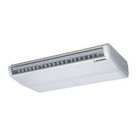
Mitsubishi Heavy Industries FDE140VNVG Technical Manual (476 pages)
INVERTER PACKAGED AIR-CONDITIONERS
Brand:
Mitsubishi Heavy Industries
| Category:
Air Conditioner
| Size: 77.55 MB
Table of Contents
) Restrictions on Unit Installation and Use
361
The Packaging
97
Anomalous Stop of the Unit Due to Rising of High Pressure
99
Deliver the Unit as Close as Possible to the Installation Site before Removing It from
99
Radio or TV Interference
99
And Service of the Unit Safely
99
Where an Existing Pipe System Is Utilized, Different One-Way Pipe Length Restrictions Should Apply Depending on Its Pipe Size
100
For more Information, Please See "5. UTILIZATION of EXISTING PIPING
100
If Touching with an Internal Component, It will Generate Abnormal Sounds And/Or Vibrations
100
Fix both Liquid and Gas Service Valves at the Valve Main Bodies as Illustrated on the Right
100
In Installing the Unit, Fix the Unit's Legs with Bolts Specified on the above
107
Refer to the above Illustrations for Information Regarding Concrete Foundations
107
How to Remove the Side Cover
108
Its Form
108
Other Equipment
359
Snow Cover Surface, and
359
Indoor Unit Connected
360
Table of Contents
361
Grommet (Heat Pump Type Only) Drain Elbow (Heat Pump Type Only) Reducer Set Ø9.52
360
Hole Core Drill (65Mm in Diameter)
360
Spanner Wrench
360
Ø6.35
363
Ø12.7
363
Fdt, Fden Fdu, Fdum, Srk
363
Ø9.52
363
Ø15.88
363
An Abnormal Overheat Accident)
364
Penetrates into the Box.)
364
In the Malfunctioning or a Failur
364
Always Use a Three-Core Cable Fo
364
Acccident such as an Electric Sh
364
Electrical Installation Work Must be
364
Use Polychloroprene Sheathed Fl
364
Terminal Connection and then a
364
Do Not Use any Supply Cord Ligh
364
Ordinary Tough Rubber Sheathe
364
Fdt, Fden, Fdu
365
Of the Unit
366
Install the Unit on the Base so
366
That the Bottom Is Higher than
366
Haulage and Installation
367
When a Unit Is Hoisted with Slings for Haulage, Take into Consideration the Offset of Its Gravity
367
Center Position. if Not Properly Balanced, the Unit Can be Thrown Off-Balance and Fall
367
The Right Hand Side of the Unit as Viewed from the Front (Diffuser Side) Is Heavier
367
Torque Wrench
367
〇 a Place Where the Unit will Not be Affected by Heat Radiation from Other Heat Source
368
Do Not Install the Unit in Places Which Exposed to Sea Breeze (E.g. Coastal Area) or Calcium Chloride (E.g. Snow Melting Agent), Exposed to Ammonia Substance (E.g. Organic Fertilizer)
368
〇 a Place Where Strong Wind will Not Blow against the Outlet Air Blow of the Unit
368
〇 a Place Where Snow will Not Accumulate
368
〇 a Place Where It Can be Free from Danger of Flammable Gas Leakage
368
〇 a Place Where Drain Water Can be Disposed Without any Trouble
368
〇 a Place Where the Unit Is Not Exposed to Oil Splashes
368
〇 a Place Where It Is Horizontal, Stable and Can Endure the Unit Weight and will Not Allow Vibration Transmittance
368
Selection of Installation Location for the Outdoor Unit
368
〇 a Place Where It Can be Free from Possibility of Bothering Neighbors Due to Noise or Exhaust Air from the Unit
368
Determination of Pipe Size
369
Determine Refrigerant Pipe Size Pursuant to the Following Guidelines Based on the Indoor Unit Specifications.
369
Refrigerant Pipe Wall Thickness and Material
369
On-Site Piping Work
369
Give Sufficient Protection to a Pipe End (Compressed and Blazed, or with an Adhesive Tape) so
369
Flare Connection Is Used between the Unit and Refrigerant Pipe. Flare a Pipe after Engaging a
369
Outdoor Unit Connected
369
Select Refrigerant Pipes of the Table Shown on the Right Wall Thickness and Material as Specified for each Pipe Size
369
Select Pipes Having a Wall Thickness Larger than the Specified Minimum Pipe Thickness
369
〇 a Place Where Chemical Substances Like Sulfuric Gas, Chloric Gas, Acid and Alkali (Includingammonia), Which Can
375
Be Sure to Select a Suitable Installation Place in Consideration of Following Conditions
375
〇 a Place Where the Unit Can be Kept Away 5M or more from TV Set And/Or Radio Receiver in Order to Avoid any
375
Restrictions on Unit Installation and Use
376
So that Strong Wind will Not Blow against the Outdoor Heat Exchanger Directly
376
Refrigerant Piping Work
376
Carry out the on Site Piping Work with the Service Valve Fully Closed
377
Bend a Pipe to a Radius as Large as Practical.(R100~R150) Do Not Bend a Pipe Repeatedly to Correct
377
Refrigerant Piping (Branch Pipel)
377
Take Care so that Installed Pipes May Not Touch Components Within a Unit
377
Do Not Turn on the Power until T
378
Do Not Use a Condensive Capaci
379
When Cables Are Connected, Ma
379
Fasten Cables so that May Not to
379
Do Not Lay Electronic Control Cab
379
For Power Source Cables, Use Co
379
The Installation of an Impulse W
379
A Grounding Wire Must be Conn
379
Ground the Unit. Do Not Connect the if Impropery Grounded, an Elect
379
Braided Cord
379
Electrical Installation Work Must be
379
Hyper Inverter Packaged Air-Conditioners
423
General Information
424
GENERAL INFORMATION (1) How to Read the Model Name Example: FDE 40 VG
424
How to Read the Model Name
424
Model Name (Ceiling Suspended Type)
424
Product Capacity
424
Series Code
424
Table of Models
424
Table of System Combinations
424
Indoor Units
425
Specifications
425
Outdoor Units
429
Operation Chart
436
Application Data
439
Electrical Wiring
439
Exterior Dimensions
439
Maintenance Data
439
Noise Level
439
Outline of Operation Control by Microcomputer
439
Piping System
439
Range of Usage & Limitations
439
Selection Chart
439
Temperature and Velocity Distribution
439
Micro Inverter Packaged Air-Conditioners
440
Electrical W
440
General Information
440
How to Read the Model Name
440
Table of Models
441
Table of System Combinations
441
Indoor Units
442
Specifications
442
Outdoor Units
447
Operation Chart
455
Application Date
458
Electrical Wiring
458
Exterior Dimensions
458
Maintenance Data
458
Noise Level
458
Outline of Operation Control by Microcomputer
458
Piping System
458
Range of Usage & Limitations
458
Selection Chart
458
Temperature and Velocity Distribution
458
Advertisement
Advertisement
Related Products
Mitsubishi Heavy Industries FDE140VNAVWH
Mitsubishi Heavy Industries FDE140VNAWPVH
Mitsubishi Heavy Industries FDE140VNAWTVH
Mitsubishi Heavy Industries FDE140VNXVG
Mitsubishi Heavy Industries FDE140VNXPVG
Mitsubishi Heavy Industries FDE140VNXTVG
Mitsubishi Heavy Industries FDE140VNPVG
Mitsubishi Heavy Industries FDE140VNTVG
Mitsubishi Heavy Industries FDE140VSAWPVH
Mitsubishi Heavy Industries FDE140VSAWTVH
Mitsubishi Heavy Industries Categories
Air Conditioner
Remote Control
Heat Pump
Engine
Control Systems
More Mitsubishi Heavy Industries Manuals
Login
Sign In
OR
Sign in with Facebook
Sign in with Google
Upload manual
Upload from disk
Upload from URL