Sign In
Upload
Manuals
Brands
Mitsubishi Heavy Industries Manuals
Air Conditioner
FDC224KXZPE1
Mitsubishi Heavy Industries FDC224KXZPE1 Manuals
Manuals and User Guides for Mitsubishi Heavy Industries FDC224KXZPE1. We have
1
Mitsubishi Heavy Industries FDC224KXZPE1 manual available for free PDF download: Service Manual
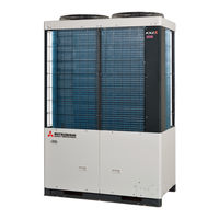
Mitsubishi Heavy Industries FDC224KXZPE1 Service Manual (152 pages)
VRF Inverter Multi-System, Outdoor units
Brand:
Mitsubishi Heavy Industries
| Category:
Air Conditioner
| Size: 18.69 MB
Table of Contents
Contents
2
Icon Display
3
Outline of Operation Control by Microcomputer
3
Remote Control
3
Wired Remote Control
4
Wireless Remote Control
5
CPU Reset
6
Operation Control Function by the Wired Remote Control
6
Power Failure Compensation Function (Electric Power Source Failure)
6
Switching Sequence of the Operation Mode Switches of Remote Control
6
Operation and Setting from Remote Control
8
Dehumidifying Operation
11
Operation Control Function by the Indoor Control
11
Operations of Functional Items During Cooling/Heating
11
Timer Operation
11
Remote Control Display During the Operation Stop
12
Rc-E5
12
Hot Start (Cold Draft Prevention at Heating)
12
Combination of Patterns Which Can be Set for the Timer Operations
12
Auto Swing Control
13
Ending Condition
13
Hot Keep
13
Cooling
14
Heating
14
Thermostat Operation
14
Fan Control During Cooling Thermostat off
15
Fan Control During Heating Thermostat off
15
Compressor Inching Prevention Control
16
Drain Pump Control
16
Filter Sign
16
Cooling, Dehumidifying Frost Protection
17
Drain Motor (DM) Control
17
Operation Check/Drain Pump Test Run Operation Mode
17
High Ceiling Control
18
External Input/Output Control (Cnt or Cnta)
18
Anomalous Fan Motor
18
Abnormal Temperature Thermistor Wire/Short-Circuit Detection
18
Output for External Control (Remote Display)
19
Operation Permission/Prohibition
20
Selection of Cooling/Heating External Input Function
21
High Power Operation/Energy-Saving Operation
22
Return Air Temperature Compensation
22
Room Temperature Detection Temperature Compensation During Heating
22
Warm-Up Control
22
The Operation Judgment Is Executed Every 5 Minutes
23
Home Leave Mode
23
IU Overload Alarm/Peak-Cut Time
23
Fan Circulator Operation
23
Normal Control
24
Operation Control Function by the Outdoor Control
24
Compressor Operation Range
25
Maximum Compressor Frequency
25
Minimum Compressor Frequency
25
Outdoor Fan Speed and Fan Motor Rotation Speed
26
Fan Control During Cooling
26
Outdoor Fan Heating Control
26
Outdoor Fan Control
26
Defrost Control
27
Temperature Condition of Defrosting
27
High Pressure Protective Control/Error
28
Low Pressure Protective Control/Error
28
Protective Control
28
Test Run
28
Optional Controls
29
Demand Control
30
Demand Control from Indoor Unit
31
Control Contents
32
End Condition
32
Silent Mode Control
32
Start Conditions
32
Setting Method of Outdoor Fan Control
33
External Output
33
Outdoor Fan Snow Protection Control
33
End Conditions of Outdoor Fan Snow Protection Control
33
Outdoor Operation Mode
34
Emergency Stop Control
36
Forced Cooling/Heating Operation
36
Pump down Operation Control for Removal of the Unit
37
VTCC : Variable Temperature and Capacity Control
38
Data Output
40
7-Segment Display and Operation Data Retention
40
Individual Definition of Display Contents
41
Operation Information
42
Control Status
46
Definition of Signal
46
Protection Control Status
46
Compressor Stop Causes
47
Indoor Unit Indicate Data
48
Saving of Operation Data
48
Outdoor Unit Indicate Data
49
Output of PCB Hardware
51
Control PCB
57
Outdoor PCB Setting
57
Indoor PCB Setting
58
Basics of Troubleshooting
59
Checking 15V on the Control PCB
60
Explanation of Troubleshooting
60
Inspection of Short-Circuit on the Power Transistor Module Terminals
60
Inverter Checker for Diagnosis of Inverter Output
61
Outdoor Unit Check Points
62
Contents of Troubleshooting
63
List of Inspection Displays
63
Operates but Does Not Cool
64
Troubleshooting Procedures
64
Operates but Does Not Heat
65
Earth Leakage Breaker Activated
66
Excessive Noise/Vibration
67
Louver Motor Anomaly
70
Power Source System Anomaly (Power Source to Indoor Unit PCB)
71
Power Source System Error (Power Source to Remote Control)
72
Wait
73
No Display
79
Remote Control Communication Error
80
Duplicated Indoor Unit Address
81
Outdoor Unit Signal Line Error
82
Communication Error During Operation
83
Indoor Heat Exchanger Temperature Thermistor Anomaly (Thi-R)
84
Indoor Return Air Temperature Thermistor Anomaly (Thi-A)
85
Drain Trouble
86
Excessive Number of Indoor Units by Controlling One Remote Control
87
Address Setting Error between Master and Slave Indoor Units
88
Address Setting Error by Mixed Setting Method
89
Indoor DC Fan Motor Anomaly
90
Address Setting Error of Master and Slave Indoor Units
91
Indoor Unit Operation Check, Drain Motor Check Mode Anomaly
92
Indoor DC Fan Motor Rotation Speed Anomaly
93
Defective Panel Switch Operation (FDT)
94
Remote Control Temperature Thermistor Anomaly (Thc)
95
Duplicated Outdoor Unit Address No.
96
Open L3 Phase on Power Source at Primary Side
97
Discharge Pipe Temperature Error (Tho-D)
98
Outdoor Heat Exchanger Temperature Thermistor (Tho-R) Anomaly
99
Subcooling Coil Temperature Thermistor (Tho-SC,-H) Anomaly
99
Outdoor Air Temperature Thermistor Anomaly (Tho-A)
100
Discharge Pipe Temperature Thermistor Anomaly (Tho-D)
101
High Pressure Anomaly (63H1 Activated)
102
Power Transistor Overheat
103
Current Cut (CM1)
104
1 Applicable Model
105
2 Error Detection Method
105
Excessive Number of Indoor Units Connected
105
Excessive Total Capacity of Connection
105
Indoor Keeps Flashing Stays off
106
Liquid Flooding Anomaly (CM1)
106
Outdoor Keeps Flashing 1-Time Flash
106
3 Condition of Error Displayed
105
5 Troubleshooting
106
Communication Error between Inverter PCB and Outdoor Control PCB
107
Mixed Address Setting Methods Coexistent in same Network
108
Outdoor DC Fan Motor Anomaly
109
Is the
111
Low Pressure Anomaly
111
Save Data for 30 Minutes before Stopping in Mente PC
111
Suction Pipe Temperature Thermistor Anomaly (Tho-S)
112
Under-Dome Temperature Thermistor Anomaly (Tho-C)
112
High Pressure Sensor Anomaly (PSH)
113
Low Pressure Sensor Anomaly (PSL)
113
Anomalous Compressor by Loss of Synchronism
114
Compressor Startup Failure (CM1)
115
Table of Contents
116
Emergency Stop
116
Outdoor Unit Control PCB Replacement Procedure
117
Outdoor Unit Inverter PCB Replacement Procedure
119
Control PCB
120
Target Places Which Are Removed Harnesses and Screws
120
Installation Method to Power Transistor
121
Installationplace of Inverter PCB
121
Outdoor Unit Converter PCB Replacement Procedure
122
Voltage Measurement Points
123
Outdoor Unit Transistor Module Replacement Procedure
124
Outdoor Unit Diode Module Replacement Procedure
125
Function of Connection
126
Electrical Wiring
127
Piping System
128
Application Data
129
Installation of Outdoor Unit
129
Before Beginning Installation
130
Selecting the Installation Location
130
Installation Space (Ex. Servicing Space)
131
Refrigerant Piping
131
Restrictim on Use of Pipes
131
Unit Delivery and Installation
131
Pipe Size Selection
132
Selection of the Branch Pipe Set
132
Selection of the Branch Set for Indoor Unit Side
132
Selection of the Header Set
132
Field Piping Work
133
Piping Work
133
Air Tightness Test and Vacuuming
134
Additional Charge of Refrigerant
135
Heating and Condensation Prevention
135
Drain Piping Work
136
Electric Wiring
136
Power Source Connection
136
Wiring System Drawing
136
How to Connect Signal Cables
137
Control Settings
138
Remote Control Wiring Specifications
138
Unit Address Setting
138
Automatic Address Setting
139
Manual Address Setting
139
Address Change (Available Only with New SL)
141
7-Segment Display Indication in Automatic Address Setting
142
External Input and Output Terminals Specifications
143
Selection Switching
143
Silent Mode Setting
143
Cautions for Servicing
144
Demand Control Setting
144
Test Operation and Transfer
144
About Brazing
145
Method for Connecting the Accessory Pipe
145
Connection Example
146
Instructions for Installing the Branch Pipe Set
147
How to Select a Branching Pipe
149
How to Select a Header Set
149
Branching + Header Mixed Type Configuration
150
Branching Type Configuration
150
Example of Piping
150
Header Type Configuration
150
Advertisement
Advertisement
Related Products
Mitsubishi Heavy Industries FDC224KXZME1
Mitsubishi Heavy Industries FDC224KXZRE1
Mitsubishi Heavy Industries FDC224KXZXE1
Mitsubishi Heavy Industries FDC224KXE6
Mitsubishi Heavy Industries FDC280KXZPE1
Mitsubishi Heavy Industries FDC280KXZXE1
Mitsubishi Heavy Industries FDC200VSA
Mitsubishi Heavy Industries FDC206HEP3
Mitsubishi Heavy Industries FDC208HEN3A
Mitsubishi Heavy Industries FDC200VSA-W
Mitsubishi Heavy Industries Categories
Air Conditioner
Remote Control
Heat Pump
Engine
Control Systems
More Mitsubishi Heavy Industries Manuals
Login
Sign In
OR
Sign in with Facebook
Sign in with Google
Upload manual
Upload from disk
Upload from URL