Sign In
Upload
Manuals
Brands
Mindray Manuals
Diagnostic Equipment
Crius R9
Mindray Crius R9 Manuals
Manuals and User Guides for Mindray Crius R9. We have
2
Mindray Crius R9 manuals available for free PDF download: Service Manual
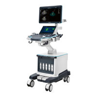
Mindray Crius R9 Service Manual (365 pages)
Diagnostic Ultrasound System
Brand:
Mindray
| Category:
Diagnostic Equipment
| Size: 31 MB
Table of Contents
Table of Contents
3
Revision History
9
Intellectual Property Statement
10
Applicable for
10
Statement
10
Responsibility on the Manufacturer Party
11
Service Contact
11
Safety Precautions
13
Meaning of Signal Words
13
Symbols
13
Meaning of Safety Symbols
13
Warning Labels
14
General Symbols
14
Safety Precautions
16
Electric Safety
16
Mechanical Safety
17
Personnel Safety
17
Other
17
Specifications
19
Overview
19
Intended Use
19
Introduction of each Unit
19
Peripherals Supported
28
Specifications
28
Dimensions & Weight
28
Electrical Specifications
28
Environmental Conditions
29
Monitor Specification
29
System Installation
31
Preparations for Installation
31
Electrical Requirements
31
Installation Conditions
32
Confirmation before Installation
33
Unpacking
33
Unpacking Process
33
Checking
36
Bare Machine Transport
37
Tool
37
Device Transport
38
Fixing Methods
38
Installing Main Unit
41
Opening up the Monitor
41
Connecting the Power Cord
41
Connecting ECG
42
Installing Probe Holder
42
Installing Gel Holder
42
Connecting the Transducer
44
Installing Peripherals
45
Connecting a Footswitch
45
Installing a Graph/Text Printer
45
Installing a Video Printer
48
Installing a Wireless Printer
49
Installing the Printer Driver in Windows Interface
49
Installing a Barcode Scanner
51
Ascending/Descending the Main Control Panel Manually
52
System Configuration
55
Running the System
55
Entering Doppler
55
System Preset
56
Printer Preset
57
Network Preset
58
Network Configuration
59
DICOM/HL7 Preset
62
Security
64
Check System Information
65
Product Principle
67
General Structure of Hardware System
67
Ultrasound Front Unit
68
Probe Board
69
TR Board
70
Engine Board
71
ECG Module
72
TEE Board
73
Ultrasound Back-End Unit
73
COME (CPU) Module
74
Independent GPU (GPU)
74
Memory Device (SSD&SATA Hard Disk)
74
PC Carrier Board
74
User I/O Interface Board
82
Wifi Module
83
Power Supply Unit
83
AC Interface Module
83
Auxiliary Output Power Isolation Transformer
84
AC-DC Module
84
DC-DC Board
84
PHV Module
84
Battery Management Board and Battery Module
85
New Power Supply Unit
86
AC-DC Module
87
To 24V Control Board
87
DC-DC Board
87
PHV Module
87
Battery Module
87
User Interaction Unit
87
Control Panel
87
Primary Display Assembly
88
Secondary Display Assembly
88
Electrical Ascending/Descending and Electromagnet
89
Function and Performance Checking Method
91
Note
91
Device Status Checking
91
Running Status
91
Working Condition
91
General Exam
92
Check Flow
92
Checking Content
92
Function Checking
94
Check Flow
95
Performance Test
101
Test Process
101
Test Content
101
Software Installation &Maintenance
109
Entering Maintenance
109
Set Installment
109
Software Installation/Restoration
112
Enter Windows
112
Software Maintenance
113
Export Log
113
Log Manager
113
Activating Operating System
115
Data Backup and Storage
118
Preset Data Management
118
Patient Data Backup and Restoration
119
Probe Check
119
Introduction on Hard Disk's Partitions
120
Adjustments
121
Adjusting Monitor
121
Adjusting Position
121
Adjusting Brightness and Contrast
124
Monitor Test
125
Touch Screen Adjustment
126
Touch Screen Brightness and Contrast Adjustment
126
Touch Screen Test
126
Control Panel Adjustment
127
Adjusting Caster
127
Field Replaceable Unit
129
Explosive View
130
Assembly Explosive View
131
Monitor Assembly (A0)
131
Monitor Support Arm Assembly (B0)
134
Main Control Panel Assembly (C0)
136
Control Panel Support Arm Assembly (D0)
144
Main Unit Assembly (E0)
147
Base Assembly (F0)
154
Base Power Box Assembly (G0)
155
Cable (H0)
157
Fusion Imaging Assembly (I0)
160
Structure and Assembly/Disassembly
163
Structure of the Complete System
163
Preparation
164
Tools Required
164
Engineers Required
164
Requirements
164
Assembly/Disassembly
165
Large/Small Probe Holders, Left Bracket of Coupling Gel Heating Cup, Intracavitary Probe Holder
167
Cup Rack Assembly
168
Wire Pothook Assembly
168
Mesh of the Base
169
Display (Monitor) Assembly
169
Control Panel Assembly
171
Handle Panel Assembly
182
Touch Screen Assembly
183
Speaker Cover Assembly
184
Left/Right Speaker Assembly
185
Upper/Lower Support Arm Cover
185
Support Arm Assembly
186
LCD Signal Connector PCBA Assembly
193
Control Panel Moving Mechanism Assembly
197
Main Unit Rear Cover Assembly
201
Main Unit Left Cover Assembly
202
Main Unit Right Cover Assembly
203
Main Unit Front-Top Cover Assembly
204
Turbine Cover
205
Turbine Protective Shell Assembly
205
Main Unit Top Cover/Main Unit Top Cover Assembly
206
Right/Left Brake Pedal
207
Machine Assembly
208
PC Main Board Assembly
215
Wireless Net Adapter
219
Antenna and Cable Assembly
220
Battery Assembly
221
IO Assembly
222
Probe Board Assembly
222
Electronics Assembly on the Base
223
HDD Assembly
231
DVD Assembly
232
Front Output Panel
234
ECG Assembly
236
Signal Cable of ECG Module
236
Mother Board Assembly
237
Housing Assembly of the Main Unit
240
Magnetic Generator Trolley
256
Magnetic Navigator
259
Installing Options
265
Installing Optional Software
265
Installation of Hardware Optional Function
267
Magnetic Transmitter Trolley Assembly
268
Probe Adapter Installation
270
Pencil Probe Signal Cable Assembly
271
Iclear Dongle
273
System Diagnosis and Support
275
General Status Indicator
275
Indicators on Control Panel
275
Display Status Indicator
276
Status of Entire Device
276
Starting Process of the Whole Machine
278
Alarming and Errors
279
The Voltage of System Power Is Abnormal
279
Abnormal Temperature
279
Battery Error
280
Fan Error
280
PHV Error
280
Board Error
281
Other Errors
281
Error Code List
282
Self Test
287
Self Test Introduction
287
Operation Procedures of Maintenance Self Test
287
User Self Test
292
Test Report
294
Care and Maintenance
297
Overview
297
Tools, Measurement Devices and Consumables
297
Routine Maintenance Items
297
Cleaning
299
System Cleaning
299
Peripherals Cleaning
303
Check
304
General Check
304
System Performance Check
304
Check for Peripherals and Optional Functions
305
Mechanical Safety Inspection
306
Electrical Safety Inspection
308
Troubleshooting of Regular Malfunctions
309
System Cannot Power on
309
Related Modules or Boards
309
Key Points Supporting Troubleshooting
309
Troubleshooting
310
System Cannot Start
311
Related Modules or Boards
311
Key Points Supporting Troubleshooting
311
Troubleshooting-The System Cannot Start
311
Image Problems
312
Related Modules or Boards
312
Key Points Supporting Troubleshooting
312
Troubleshooting-Imaging
313
Probe Socket System Malfunction
314
Related Modules or Boards
314
Key Points Supporting Troubleshooting
314
Troubleshooting of Probe Socket System
314
IO Interface System Failure
314
Key Points Supporting Troubleshooting
315
Troubleshooting of IO Interface System
316
Control Panel Failure
317
Related Modules or Boards
317
Key Points Supporting Troubleshooting
317
Troubleshooting of Control Panel
317
LCD Display Failure
318
Related Modules or Boards
318
Key Points Supporting Troubleshooting
318
Troubleshooting of the Monitor
319
ECG Module Failure
319
Related Modules or Boards
319
Key Points Supporting Troubleshooting
320
Troubleshooting for ECG Module
320
Troubleshooting
320
Related Modules or Boards
320
Drive Troubleshooting
320
Appendix A Electrical Safety Inspection
323
Appendix B Phantom Usage Illustration
341
Appendix C Description of Self Test Items
343
Advertisement
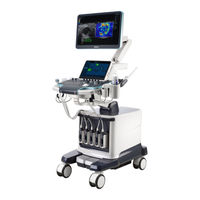
Mindray Crius R9 Service Manual (359 pages)
Diagnostic Ultrasound System
Brand:
Mindray
| Category:
Diagnostic Equipment
| Size: 31 MB
Table of Contents
Table of Contents
3
Revision History
9
Intellectual Property Statement
10
Applicable for
10
Statement
10
Responsibility on the Manufacturer Party
11
Service Contact
11
Safety Precautions
13
Meaning of Signal Words
13
Symbols
13
Meaning of Safety Symbols
13
Warning Labels
14
General Symbols
14
Safety Precautions
16
Electric Safety
16
Mechanical Safety
17
Personnel Safety
17
Other
17
Specifications
19
Overview
19
Intended Use
19
Introduction of each Unit
19
Peripherals Supported
26
Specifications
26
Dimensions & Weight
26
Electrical Specifications
27
Environmental Conditions
27
Monitor Specification
28
System Installation
29
Preparations for Installation
29
Electrical Requirements
29
Installation Conditions
30
Confirmation before Installation
31
Unpacking
31
Unpacking Process
31
Checking
34
Bare Machine Transport
35
Tool
35
Device Transport
36
Fixing Methods
36
Installing Main Unit
39
Opening up the Monitor
39
Connecting the Power Cord
39
Connecting ECG
40
Installing Probe Holder
40
Installing Gel Holder
40
Connecting the Transducer
42
Installing Peripherals
43
Connecting a Footswitch
43
Installing a Graph/Text Printer
43
Installing a Video Printer
46
Installing a Wireless Printer
47
Installing the Printer Driver in Windows Interface
47
Installing a Barcode Scanner
49
Ascending/Descending the Main Control Panel Manually
50
System Configuration
53
Running the System
53
Entering Doppler
53
System Preset
54
Printer Preset
55
Network Preset
56
Network Configuration
57
DICOM/HL7 Preset
60
Security
62
Check System Information
63
Product Principle
65
General Structure of Hardware System
65
Ultrasound Front Unit
66
Probe Board
67
TR Board
68
Engine Board
69
ECG Module
70
TEE Board
71
Ultrasound Back-End Unit
71
COME (CPU) Module
72
Independent GPU (GPU)
72
Memory Device (SSD&SATA Hard Disk)
72
PC Carrier Board
72
User I/O Interface Board
80
Wifi Module
81
Power Supply Unit
81
AC Interface Module
81
Auxiliary Output Power Isolation Transformer
82
AC-DC Module
82
DC-DC Board
82
PHV Module
82
Battery Management Board and Battery Module
83
New Power Supply Unit
84
AC-DC Module
85
To 24V Control Board
85
DC-DC Board
85
PHV Module
85
Battery Module
85
User Interaction Unit
85
Control Panel
85
Primary Display Assembly
86
Secondary Display Assembly
86
Electrical Ascending/Descending and Electromagnet
87
Function and Performance Checking Method
89
Note
89
Device Status Checking
89
Running Status
89
Working Condition
89
General Exam
90
Check Flow
90
Checking Content
90
Function Checking
92
Check Flow
93
Performance Test
99
Test Process
99
Test Content
99
Software Installation &Maintenance
107
Entering Maintenance
107
Set Installment
107
Software Installation/Restoration
110
Enter Windows
110
Software Maintenance
111
Export Log
111
Log Manager
111
Fast Startup
113
Activating Operating System
113
Data Backup and Storage
116
Preset Data Management
116
Patient Data Backup and Restoration
117
Probe Check
117
Introduction on Hard Disk's Partitions
118
Adjustments
119
Adjusting Monitor
119
Adjusting Position
119
Adjusting Brightness and Contrast
120
Monitor Test
121
Touch Screen Adjustment
122
Touch Screen Brightness and Contrast Adjustment
122
Touch Screen Test
122
Control Panel Adjustment
123
Adjusting Caster
123
Field Replaceable Unit
125
Explosive View
126
Assembly Explosive View
127
Monitor Assembly (A0)
127
Monitor Support Arm Assembly (B0)
131
Main Control Panel Assembly (C0)
133
Control Panel Support Arm Assembly (D0)
141
Main Unit Assembly (E0)
144
Base Assembly (F0)
151
Base Power Box Assembly (G0)
152
Cable (H0)
154
Fusion Imaging Assembly (I0)
157
Structure and Assembly/Disassembly
159
Structure of the Complete System
159
Preparation
160
Tools Required
160
Engineers Required
160
Requirements
160
Assembly/Disassembly
161
Large/Small Probe Holders, Left Bracket of Coupling Gel Heating Cup, Intracavitary Probe Holder
163
Cup Rack Assembly
164
Wire Pothook Assembly
164
Mesh of the Base
165
Display (Monitor) Assembly
165
Control Panel Assembly
167
Handle Panel Assembly
178
Touch Screen Assembly
179
Speaker Cover Assembly
180
Left/Right Speaker Assembly
181
Upper/Lower Support Arm Cover
181
Support Arm Assembly
182
LCD Signal Connector PCBA Assembly
187
Bale of Wire for the Monitor/Side Control Panel Base/Base Assembly
188
Control Panel Moving Mechanism Assembly
190
Main Unit Rear Cover Assembly
195
Main Unit Left Cover Assembly
195
Main Unit Right Cover Assembly
196
Main Unit Front-Top Cover Assembly
197
Turbine Cover
198
Turbine Protective Shell Assembly
198
Main Unit Top Cover/Main Unit Top Cover Assembly
199
Right/Left Brake Pedal
200
Machine Assembly
201
PC Main Board Assembly
208
Wireless Net Adapter
212
Antenna and Cable Assembly
213
Battery Assembly
214
IO Assembly
215
Probe Board Assembly
215
Electronics Assembly on the Base
216
HDD Assembly
224
DVD Assembly
225
Front Output Panel
227
ECG Assembly
229
Signal Cable of ECG Module
229
Mother Board Assembly
230
Housing Assembly of the Main Unit
233
Magnetic Generator Trolley
249
Magnetic Navigator
252
Installing Options
257
Installing Optional Software
257
Installation of Hardware Optional Function
259
Magnetic Transmitter Trolley Assembly
260
Probe Adapter Installation
262
Pencil Probe Signal Cable Assembly
263
Iclear Dongle
265
System Diagnosis and Support
267
General Status Indicator
267
Indicators on Control Panel
267
Display Status Indicator
268
Status of Entire Device
268
Starting Process of the Whole Machine
270
Alarming and Errors
271
The Voltage of System Power Is Abnormal
271
Abnormal Temperature
271
Battery Error
272
Fan Error
272
PHV Error
272
Board Error
273
Other Errors
273
Error Code List
274
Self Test
279
Self Test Introduction
279
Operation Procedures of Maintenance Self Test
279
User Self Test
284
Test Report
286
Care and Maintenance
289
Overview
289
Tools, Measurement Devices and Consumables
289
Routine Maintenance Items
289
Cleaning
291
System Cleaning
291
Peripherals Cleaning
295
Check
296
General Check
296
System Performance Check
296
Check for Peripherals and Optional Functions
297
Mechanical Safety Inspection
298
Electrical Safety Inspection
300
Troubleshooting of Regular Malfunctions
301
System Cannot Power on
301
Related Modules or Boards
301
Key Points Supporting Troubleshooting
301
Troubleshooting
302
System Cannot Start
303
Related Modules or Boards
303
Key Points Supporting Troubleshooting
303
Troubleshooting-The System Cannot Start
303
Image Problems
304
Related Modules or Boards
304
Key Points Supporting Troubleshooting
304
Troubleshooting-Imaging
305
Probe Socket System Malfunction
306
Related Modules or Boards
306
Key Points Supporting Troubleshooting
306
Troubleshooting of Probe Socket System
306
IO Interface System Failure
306
Key Points Supporting Troubleshooting
307
Troubleshooting of IO Interface System
308
Control Panel Failure
309
Related Modules or Boards
309
Key Points Supporting Troubleshooting
309
Troubleshooting of Control Panel
309
LCD Display Failure
310
Related Modules or Boards
310
Key Points Supporting Troubleshooting
310
Troubleshooting of the Monitor
311
ECG Module Failure
311
Related Modules or Boards
311
Key Points Supporting Troubleshooting
312
Troubleshooting for ECG Module
312
Troubleshooting
312
Related Modules or Boards
312
Drive Troubleshooting
312
Appendix A Electrical Safety Inspection
315
Appendix B Phantom Usage Illustration
335
Appendix C Description of Self Test Items
337
Advertisement
Related Products
Mindray Crius R9S
Mindray BeneHeart C1A
Mindray BeneHeart C2A
Mindray CW2s
Mindray C6-2Gs
Mindray C7-3E
Mindray C11-3s
Mindray C5-1s
Mindray C5-1U
Mindray C11-3U
Mindray Categories
Medical Equipment
Diagnostic Equipment
Measuring Instruments
Monitor
Water Pump
More Mindray Manuals
Login
Sign In
OR
Sign in with Facebook
Sign in with Google
Upload manual
Upload from disk
Upload from URL