Sign In
Upload
Manuals
Brands
Minarik Manuals
Inverter
MM23000 Series
Minarik MM23000 Series Manuals
Manuals and User Guides for Minarik MM23000 Series. We have
2
Minarik MM23000 Series manuals available for free PDF download: User Manual
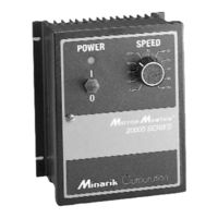
Minarik MM23000 Series User Manual (84 pages)
SCR, Adjustable Speed Drives for DC Brush Motors
Brand:
Minarik
| Category:
Inverter
| Size: 1 MB
Table of Contents
Safety Warnings
3
Table of Contents
4
Specifications
9
Specifications (Continued)
10
Suffix Definitions
10
Dimensions
11
Figure 1. MM23001 and MM23011 Dimensions
11
Figure 2. MM23001C-Q and MM23011C-Q Dimensions
12
Figure 3. MM23101 and MM23111 Dimensions
13
Figure 4. MM23201 and MM23211 Dimensions
14
Figure 5. MM23401 and MM23411 Dimensions
15
Figure 6. MM23501 Dimensions
16
Figure 7. MM23071 and MM23072 Dimensions
17
Figure 8. Heat Sink Dimensions
18
Installation
19
Chassis Drives
19
Mounting
19
Wiring
20
Shielding Guidelines
21
Heat Sinking
22
Quick-Disconnect Terminal Block (C-Q Drives Only)
23
Figure 9. Quick-Disconnect Terminal Block
23
Speed Adjust Potentiometer
24
Figure 10. Speed Adjust Potentiometer
24
Chassis Drive Connections
25
Power, Fuse and Motor Connections
25
Table 1. Recommended Line Fuse Sizes
27
Table 2. Field Output Connections
28
Figure 11. Chassis Drive Connections
29
Figure 12. MM23201C-Q and MM23011C-Q Connections
30
Voltage Follower
31
Figure 13. Voltage Follower Connections
31
Cased Drives
32
Mounting (NEMA 1 Enclosures)
32
Mounting (NEMA 4X and NEMA 12 Enclosures)
33
Heat Sinking
34
Line Fusing
34
Connections
35
Table 3. Field Output Connections
36
Figure 14. Cased Drive Connections
37
Current Limit LED (C Models Only)
38
Meter Header Block (Cased C Models Only)
38
MM23001C-Q, MM23071, and MM23072 Diagnostic Leds
39
Operation
40
Before Applying Power
40
Voltage Select Switches
41
Input Voltage Select (SW501)
41
Armature Voltage Select (SW502)
41
Figure 15. Voltage Switches
41
Startup
42
MM23001, MM23011, MM23071, and MM23072
42
MM23101, MM23111, MM23401, and MM23411
42
MM23201 and MM23211
43
Mm23501
44
Starting and Stopping Methods
45
Line Starting and Line Stopping
45
Inhibit Terminals
46
Figure 16. INHIBIT Terminals
46
Decelerating to Minimum Speed
47
Figure 17. Run/Decelerate to Minimum Speed Switch
47
Dynamic Braking
48
Figure 18. Dynamic Brake Connection
49
Table 4. Minimum Recommended Dynamic Brake Resistor Values
49
Calibration
50
Minimum Speed (Min Spd)
51
Maximum Speed (Max Spd)
51
Torque
52
Ir Compensation (Ir Comp)
53
Figure 19. Recommended Torque and IR COMP Settings
54
Acceleration (Accel)
55
Deceleration (Decel)
56
Application Notes
57
Multiple Fixed Speeds
57
Figure 20. Multiple Fixed Speeds
57
Adjustable Speeds Using Potentiometers in Series
58
Figure 21. Adjustable Fixed Speeds Using
58
Potentiometers in Series
58
Independent Adjustable Speeds
59
Figure 22. Independent Adjustable Speeds
59
RUN/JOG Switch
60
RUN/JOG Switch Option #1
60
Figure 23. RUN/JOG Switch Connection to Inhibit Plug (Option #1)
60
RUN/JOG Switch Option #2
61
Figure 24. RUN/JOG Switch Connection to
61
Speed Adjust Potentiometer (Option #2)
61
Leader-Follower Application
62
Figure 25. Leader-Follower Application
62
Single Speed Potentiometer Control of Multiple Drives
63
Figure 26. Single Speed Potentiometer Control of Multiple Drives
63
Reversing
64
Figure 27. Reversing Circuit Connection
64
Reversing with a DIGI-LOK Controller
65
Figure 28. Reversing with a DLC600
65
Troubleshooting
66
Before Troubleshooting
66
Figure 29. MM23000 Series Block Diagram
70
Figure 30. MM23101, MM23111, MM23401 and MM23411
71
Terminal Block Connections
71
Figure 31. MM23201 and MM23211 Terminal Block Connections
72
Figure 32. MM23501 Terminal Block Connections
73
Replacement Parts
74
Table 5. Replacement Parts
74
CE Compliance
76
Line Filters
77
Table 6. Corcom® Filters
77
Armature Filters
78
Table 7. Minarik Filters
78
Advertisement
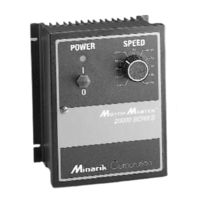
Minarik MM23000 Series User Manual (86 pages)
SCR, Adjustable Speed Drives for DC Brush Motors
Brand:
Minarik
| Category:
Inverter
| Size: 3 MB
Table of Contents
Safety Warnings
4
Table of Contents
5
Specifications
10
Specifications (Continued)
11
Suffix Definitions
11
Dimensions
12
Figure 1. MM23001 and MM23011 Dimensions
12
Figure 2. MM23001C-Q and MM23011C-Q Dimensions
13
Figure 3. MM23101 and MM23111 Dimensions
14
Figure 4. MM23201 and MM23211 Dimensions
15
Figure 5. MM23401 and MM23411 Dimensions
16
Figure 6. MM23501 Dimensions
17
Figure 7. MM23071 and MM23072 Dimensions
18
Figure 8. Heat Sink Dimensions
19
Installation
20
Chassis Drives
20
Mounting
20
Wiring
21
Shielding Guidelines
22
Heat Sinking
23
Quick-Disconnect Terminal Block (C-Q Drives Only)
24
Figure 9. Quick-Disconnect Terminal Block
24
Speed Adjust Potentiometer
25
Figure 10. Speed Adjust Potentiometer
25
Chassis Drive Connections
26
Power, Fuse and Motor Connections
26
Table 1. Recommended Line Fuse Sizes
28
Table 2. Field Output Connections
29
Figure 11. Chassis Drive Connections
30
Figure 12. MM23201C-Q and MM23011C-Q Connections
31
Voltage Follower
32
Figure 13. Voltage Follower Connections
32
Cased Drives
33
Mounting (NEMA 1 Enclosures)
33
Mounting (NEMA 4X and NEMA 12 Enclosures)
34
Heat Sinking
35
Line Fusing
35
Connections
36
Table 3. Field Output Connections
37
Figure 14. Cased Drive Connections
38
Current Limit LED (C Models Only)
39
Meter Header Block (Cased C Models Only)
39
MM23001C-Q, MM23071, and MM23072 Diagnostic Leds
40
Operation
41
Before Applying Power
41
Voltage Select Switches
42
Input Voltage Select (SW501)
42
Armature Voltage Select (SW502)
42
Figure 15. Voltage Switches
42
Startup
43
MM23001, MM23011, MM23071, and MM23072
43
MM23101, MM23111, MM23401, and MM23411
43
MM23201 and MM23211
44
Mm23501
45
Starting and Stopping Methods
46
Line Starting and Line Stopping
46
Inhibit Terminals
47
Figure 16. INHIBIT Terminals
47
Decelerating to Minimum Speed
48
Figure 17. Run/Decelerate to Minimum Speed Switch
48
Dynamic Braking
49
Figure 18. Dynamic Brake Connection
50
Table 4. Minimum Recommended Dynamic Brake Resistor Values
50
Calibration
51
Minimum Speed (Min Spd)
52
Maximum Speed (Max Spd)
52
Torque
53
Ir Compensation (Ir Comp)
54
Figure 19. Recommended Torque and IR COMP Settings
55
Acceleration (Accel)
56
Deceleration (Decel)
57
Application Notes
58
Multiple Fixed Speeds
58
Figure 20. Multiple Fixed Speeds
58
Adjustable Speeds Using Potentiometers in Series
59
Figure 21. Adjustable Fixed Speeds Using
59
Independent Adjustable Speeds
60
RUN/JOG Switch
61
RUN/JOG Switch Option #1
61
Figure 23. RUN/JOG Switch Connection to Inhibit Plug (Option #1)
61
RUN/JOG Switch Option #2
62
Figure 24. RUN/JOG Switch Connection to
62
Leader-Follower Application
63
Figure 25. Leader-Follower Application
63
Single Speed Potentiometer Control of Multiple Drives
64
Figure 26. Single Speed Potentiometer Control of Multiple Drives
64
Reversing
65
Figure 27. Reversing Circuit Connection
65
Reversing with a DIGI-LOK Controller
66
Figure 28. Reversing with a DLC600
66
Troubleshooting
67
Before Troubleshooting
67
Figure 29. MM23000 Series Block Diagram
71
Figure 30. MM23101, MM23111, MM23401 and MM23411
72
Terminal Block Connections
72
Figure 31. MM23201 and MM23211 Terminal Block Connections
73
Figure 32. MM23501 Terminal Block Connections
74
Replacement Parts
75
Table 5. Replacement Parts
75
CE Compliance
77
Line Filters
78
Table 6. Corcom® Filters
78
Armature Filters
79
Table 7. Minarik Filters
79
Advertisement
Related Products
minarik MM21051C
minarik MM21151C
minarik MM21251C
Minarik MM23101B
Minarik MMXL Series
Minarik MM30000 Series
Minarik MM31002A
Minarik MM31610A
Minarik MM32002A
Minarik MM31640A
Minarik Categories
DC Drives
Controller
Inverter
Control Unit
Computer Hardware
More Minarik Manuals
Login
Sign In
OR
Sign in with Facebook
Sign in with Google
Upload manual
Upload from disk
Upload from URL