Sign In
Upload
Manuals
Brands
Minarik Manuals
DC Drives
BOSS Series
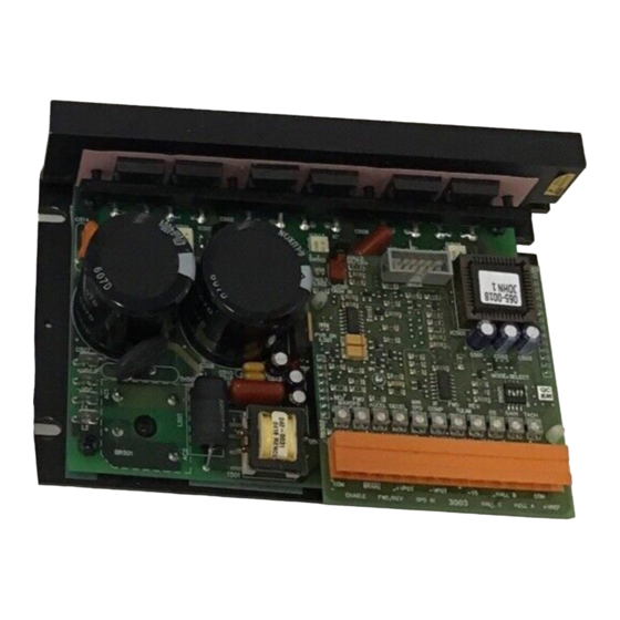
Minarik BOSS Series DC Drive Manuals
Manuals and User Guides for Minarik BOSS Series DC Drive. We have
2
Minarik BOSS Series DC Drive manuals available for free PDF download: User Manual
Minarik BOSS Series User Manual (92 pages)
Brushless Drives
Brand:
Minarik
| Category:
DC Drives
| Size: 0 MB
Table of Contents
Table of Contents
6
Specifications
11
Dimensions
12
Figure 1. BOSS Series Dimensions
12
Figure 2. BOSS DB Regen Dump Circuit Dimensions
13
Installation Drive Mounting
14
Wiring
15
Shielding Guidelines
16
Fusing
17
Table 1. Recommended Replacement Line Fuse Sizes
17
Plug-In Card Mounting
18
Figure 3. Plug-In Card Installation
19
Speed Adjust Potentiometer Mounting
20
Figure 4. Speed Adjust Potentiometer Mounting
20
Quick-Connect Terminal Block
21
Figure 5. Quick-Connect Terminal Plug
21
Motherboard Connections
22
Power Connections
22
Line Fusing
23
Power Switch
23
Figure 6. Motherboard Connections for (A) DC Input Voltage and
24
Motor Connections
25
Figure 7. Motherboard Connections for Three-Phase Motor
25
Regen Dump Circuit
26
Using the Dump Circuit with a DC Power Source
26
Figure 8. Regen Dump Circuit Connections
27
BOSS-4Q Installation
28
BOSS-4Q Terminal Descriptions
28
BOSS-4Q Plug-In Card Connections (TB501)
30
ENABLE/DISABLE Switch
30
RUN/BRAKE Switch
30
FWD/REV Switch
30
Speed Adjust Potentiometer Connections
30
Figure 9. BOSS-4Q Terminal Connections
31
Motor Hall Sensors
32
Table 2. BOSS-4Q ENABLE/BRAKE Configuration Options
32
Figure 10. BOSS-4Q Sensor Connections
33
Voltage Follower
34
Figure 15. BOSS-4Q Voltage Follower Connections
34
Motor Hall Sensor Header SW502
35
Figure 16. BOSS-4Q Motor Hall Sensor Header
35
Mode Select Switches (SW501)
36
Figure 17. BOSS-4Q Mode Select Switches
37
Table 3. Mode Select Switch Settings
37
TB504 Drive Diagnostics
38
Figure 18. BOSS-4Q TB504 Pin Assignments
38
Table 4. Drive Diagnostics (All Signals Referenced to Pin 4)
39
BOSS-CM Installation
41
BOSS-CM Terminal Descriptions
41
BOSS-CM Plug-In Card Connections to TB501
43
ENABLE/DISABLE Switch
43
DIR Switch
43
Speed Adjust Potentiometer Connections
43
Figure 15. BOSS-CM Terminal Connections to TB501
45
Figure 16. Reference Potentiometer Connection for (A) Bidirectional and (B) Unidirectional Operation
46
Motor Hall Sensors
47
Figure 17. BOSS-CM External Sensor Connections
48
BOSS-CM Jumper Settings
49
Hall Sensor Spacing (J501)
49
Figure 18. BOSS-CM Jumper Locations
49
Pwm/VDC (J502)
50
Figure 19. BOSS-CM Hall Sensor Spacer Settings (J501)
50
Figure 20. BOSS-CM PWM/VDC Jumper Settings (J502)
50
Operation
51
BOSS-4Q Operation
51
Before Applying Power
51
Startup
52
To Reverse Motor Direction
52
BOSS-CM Operation
53
Operating Mode
53
Before Applying Power
53
Startup
54
To Reverse Motor Direction
54
Starting and Stopping Methods
55
Line Starting and Line Stopping
55
To Brake the Motor (BOSS-4Q Series Drives Only)
55
To Coast the Motor to a Stop Without Disconnecting Power
56
Calibration
57
BOSS-4Q Calibration
57
Figure 21. BOSS-4Q Calibration Trimpot DIP Switch and Header Layout
58
BOSS-4Q Calibration Procedure
59
Minimum Speed (Min Speed)
60
Zero Offset (Os)
60
Forward Maximum Speed (Fwd Maxspd)
61
Reverse Maximum Speed (Rev Maxspd)
61
Acceleration (Accel)
62
Deceleration (Decel)
63
Gain
63
Forward and Reverse Torque Limit (Fwd Tqlim and Rev Tqlim)
64
Tachogenerator (Tach)
66
Figure 22. BOSS-4Q Mode Select Switch Settings
67
BOSS-CM Calibration
68
Figure 23. BOSS-CM Calibration Trimpot Layout
68
Current Limit
69
Troubleshooting
71
Before Troubleshooting
71
BOSS-4Q Diagnostic Leds
72
Diagnostic Leds on the BOSS-4Q Plug-In Card
72
Power on
72
Fault
72
Diagnostic Leds on the Motherboard
72
Bus Limit
72
Figure 24. BOSS-4Q Diagnostic LED Location
73
BOSS-CM Diagnostic Leds
74
Diagnostic Leds on the BOSS-CM Plug-In Card
74
Power on
74
Fault
74
Diagnostic Leds on the Motherboard
74
Bus Limit
74
Figure 25. BOSS-CM Diagnostic LED Location
75
BOSS Commutation Sequence Diagram
82
Figure 26. Commutation Sequence Diagram
82
CE Compliance
83
AC Line Filters
84
Connections
85
CE Filter Part Numbers
86
Enclosure
86
Figure 27. BOSS Connections for CE Compliance
86
Table 5. CE Compliance Part Numbers
86
Figure 28. BOSS Shielding Connections for CE Compliance
87
Advertisement
Minarik BOSS Series User Manual (56 pages)
Brushless Drives
Brand:
Minarik
| Category:
DC Drives
| Size: 0 MB
Table of Contents
Table of Contents
5
Specifications
9
Dimensions
10
Figure 1. BOSS Series Dimensions
10
Figure 2. BOSS DB Regen Dump Circuit Dimensions
11
Installation Drive Mounting
12
Wiring
13
Shielding Guidelines
14
Fusing
15
Table 1. Recommended Line Fuse Sizes
15
Plug-In Card Mounting
16
Figure 3. Plug-In Card Installation
17
Speed Adjust Potentiometer Mounting
18
Figure 4. Speed Adjust Potentiometer Mounting
18
Quick-Connect Terminal Block
19
Figure 5. Quick-Connect Terminal Plug
19
Motherboard Connections
20
Power Connections
20
Line Fusing
21
Figure 6. Motherboard Connections for
22
Motor Connections
23
Figure 7. Motherboard Connections for Three-Phase Motor
23
Regen Dump Circuit
24
Using the Dump Circuit with a DC Power Source
24
Figure 8. Regen Dump Circuit Connections
25
BOSS-1Q Terminal Descriptions
26
BOSS-1Q Terminal Connections
28
ENABLE/DISABLE Switch
28
RUN/BRAKE Switch
28
FWD/REV Switch
28
Figure 9. BOSS-1Q Terminal Connections
29
Motor Hall Sensors
30
Figure 10. BOSS-1Q Sensor Connections
31
Voltage Follower
32
Figure 11. BOSS-1Q Voltage Signal Connections
32
Operation
33
Before Applying Power
33
Startup
34
To Reverse Motor Direction
34
Starting and Stopping Methods
35
To Brake the Motor
35
To Coast the Motor to a Stop Without Disconnecting Power
35
Line Starting and Line Stopping
36
Calibration
37
Figure 12. BOSS-1Q Calibration Trimpot Layout
38
Calibration Procedure
39
Minimum Speed (Min Spd)
40
Maximum Speed (Max Spd)
40
Acceleration (Accel)
41
Deceleration (Decel)
41
Regulation
42
Torque Limit (Tq Limit)
43
Troubleshooting
44
Before Troubleshooting
44
BOSS-1Q Diagnostic Leds
45
Diagnostic Leds on the BOSS-1Q Plug-In Card
45
Power on
45
Fault
45
Diagnostic Leds on the Motherboard
45
Bus Limit
45
Tq Limit
45
Figure 13. BOSS-1Q Diagnostic LED Location
46
Advertisement
Related Products
Minarik BOSS04-D240AC-4Q
Minarik BOSS04-D240AC-CM
Minarik BOSS15-115AC-4Q
Minarik BOSS15-115AC-CM
Minarik BOSS08-D240AC-4Q
Minarik BOSS08-D240AC-CM
Minarik BOSS08-115AC-1Q
Minarik BOSS04-115AC-1Q
Minarik BOSS15-115AC-1Q
Minarik LV Series
Minarik Categories
DC Drives
Controller
Inverter
Control Unit
Music Equipment
More Minarik Manuals
Login
Sign In
OR
Sign in with Facebook
Sign in with Google
Upload manual
Upload from disk
Upload from URL