Sign In
Upload
Manuals
Brands
Milnor Manuals
Washer
48040F7Z
Milnor 48040F7Z Manuals
Manuals and User Guides for Milnor 48040F7Z. We have
5
Milnor 48040F7Z manuals available for free PDF download: Operator's Manual, Installation And Service, Maintenance Manual
Milnor 48040F7Z Operator's Manual (346 pages)
Brand:
Milnor
| Category:
Controller
| Size: 7 MB
Table of Contents
Table of Contents
126
Vidange Trop Longue
162
Circuit À 3 Fils Désactivé
162
Trop de Temps Avant Vapeur
162
Refroidissement Trop Long
163
Contrôler la Sonde de Température
163
Niveau en Cours
163
Panne de Communication Série
163
Défaillance du Capteur de Vitesse
164
Inverseur Déclenché
164
Erreur de Défaut Externe
164
Défaut de Pression de Frein
164
Défaut de Pression de Palier
164
Messages Spécifiques Aux Modèles Miltouch-EX
164
Patins de Frein Usés
164
Commande Côté Propreté
164
Contrôler Le Système D'équilibrage/Commutateur D'excursion
165
Messages Spécifiques Aux Modèles Miltouch-EX Chargement/Déchargement Automatique Patins de Frein Usés
165
Chargement Abandonné
165
Déchargement Abandonné
165
4.2. Entrées Et Sorties Pour L'appareil de Contrôle Miltouch
165
Sorties
167
Miltouch 3 (WUMTGUIA 3.X)
167
Miltouch 2 (WUMTGUIA 2.X)
168
Détection des Balourds Et Équilibrage des Laveuses-Essoreuses (Document BICLUF02)
173
Modèles Miltouch
173
Modèles Miltouch-EX ® Différents du 72046M5K
174
Si L'opération Suivante Est un Essorage Intermédiaire
174
Si L'opération Suivante Est un Essorage Final
174
Si Le Commutateur D'excursion Est Déclenché
175
Si Le Commutateur D'excursion Ne Se Déclenche Pas
175
Modèle Miltouch-EX ® 72046M5K
175
Si L'opération Suivante Est un Essorage Intermédiaire
175
Si L'opération Suivante Est un Essorage Final
175
Si Le Commutateur D'excursion Ne Se Déclenche Pas
176
4.5. Système de Détection Déséquilibré
176
Exigences
176
Test
177
Advertisement
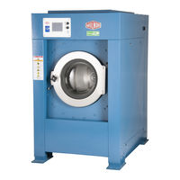
Milnor 48040F7Z Operator's Manual (110 pages)
MilTouch Controller
Brand:
Milnor
| Category:
Controller
| Size: 7 MB
Table of Contents
English
9
Table of Contents
9
Chapter 1. How to Use the Miltouch ™ Control
13
Using the Miltouch Control
13
The Home Display
13
The Wash Formula Maintenance Display
14
To Change an Existing Wash Formula
15
To Add a New Wash Formula
16
The Configuration Display
17
The Machine Configure Decisions
17
To Erase a Wash Formula
17
The Data Transfer Display
19
The Default Formulas by Laundry Type
19
Controller
21
Data Transfer with the Miltouch Programmer Software
21
How to Mount a USB Flash Drive to the Machine
21
How to Save and Transfer Wash Formulas
21
How to Save Machine Configuration Files
21
How to Transfer Machine Configuration Files to a Miltouch Machine
21
The Data Log Displays
22
The Date Selection Display
22
The Production Display
22
The Configuration and Programming Display
23
The Errors Display
23
The Inputs and Outputs Displays
24
The Run Display
26
The Names and Timers on the Run Display
26
The Machine Status Data
27
Chapter 2. How to Update the Machine Software
29
Miltouch Update: WUMTGUI/2.1
29
Does My Machine Need this Update
29
How Do I Save My Formulas and Machine Configuration
30
How Do I Update the Machine Software
31
Chapter 3. Miltouch ™ Wash Formulas
33
Miltouch Formula Decisions (Document BICLJP02)
33
Type = Type of Step
33
Time = Step Duration
33
Temp = Commanded Bath Temperature (Optional)
33
Hot = Hot Water Valve
33
Cold = Cold Water Valve
34
Third Water Valve (Optional)
34
Level = Bath Level
34
Steam (Optional)
34
C = Chemicals
34
W = When to Inject Chemicals
35
Chemical Dose = Chemical Injection Duration
35
Wash Speed
35
How to End Formula
36
Chapter 4. Troubleshooting
41
Door Opened
41
Vibration Switch Tripped
41
Too Long to Fill
41
Too Long to Drain
42
3-Wire Circuit Disabled
42
Too Long to Steam
42
Too Long to Cool
43
Check Temperature Probe(S)
43
Level Made after Drain
43
Serial Communication Failure
43
Failed Speed Sensor
43
Inverter Tripped
44
External Fault Error
44
Brake Pressure Fault
44
Bearing Pressure Fault
44
Check Flow Meter
44
Tank Pump Ol Tripped
44
Recirc Pump Ol Tripped
44
Loading Aborted
45
Discharge Aborted
45
Invalid Formula
45
Load Eye Blocked
45
Up Lock Not Made
45
Invalid Work Order
45
Invalid Goods Code
45
Invalid Customer Code
45
Can't Find Data
45
Accumulator was Reset
45
Outputs
47
Miltouch 2 (WUMTGUIA 2.X)
48
Inputs
50
Components of the Miltouch ™ Controller Circuit Boards
50
Processor Board (P/N: 08BHPAR91_)
51
Input/Output Board (P/N: 08BHF120A_)
52
4.4. Out-Of-Balance Detection System
53
Requirements
53
Testing
54
Deutsch
61
Abschnitte
62
Kapitel 1. Verwendung der Steuerung Miltouch
66
Verwenden der Miltouch ™ -Steuerung
66
Die Home Anzeige
66
Die Wash Formula Maintenance Anzeige
67
So Ändern Sie eine Bestehende Waschformel
68
Zum Hinzufügen einer Neuen Waschformel
70
Zum Löschen einer Waschformel
70
Die Konfigurations-Azeige
71
Die Maschinenkonfigurations-Entscheidungen
71
Die Standardformeln nach Wäschereityp
73
Die Data Transfer Anzeige
74
Datentransfer mit der Miltouch Programmier-Software
75
So Speichern Sie Dateien mit Maschinenkonfigurationen
75
Wie ein USB-Flashdrive an die Maschinensteuerung Angeschlossen wird
75
Die Datenauswahl-Anzeige
76
So werden Waschformeln Gespeichert und Übertragen
76
So Übertragen Sie Maschinenkonfigurationsdaten auf eine Miltouch Maschine
76
Die Anzeige Konfiguration und Programmierung
77
Die Produktions-Anzeige
77
Die Fehler-Anzeige
78
Die Anzeige Inputs and Outputs
78
Die Betrieb Anzeige (Dokument BICLJO01)
80
Die Bezeichnungen und Timer auf der Betrieb Anzeige
81
Die Maschinenstatus-Daten
81
Die Betriebszustände der Maschine
82
Die Standard- und Popup-Steuerelemente in der Betriebsanzeige
82
Aktualisierung Miltouch: WUMTGUI/2.1
84
Braucht meine Maschine diese Aktualisierung
84
Wie kann ich meine Formeln und Maschinenkonfigurationen Speichern
85
Wie Aktualisiere ich die Maschinensoftware
87
Wie kann ich meine Formeln und Konfigurationen wieder Herstellen
87
Kapitel 2. Wie wird die Maschinensoftware Aktualisiert
84
Entscheidungen Miltouch-Formeln (Dokument BICLJP02)
88
Type = Typ des Schrittes
88
Time = Schrittdauer
88
Hot = Heißwasserventil
88
Cold = Kaltwasserventil
89
Drittwasser-Ventil (Option)
89
Level = Laugen-Füllhöhe
89
Dampf (Optional)
89
W = Wann die Chemikalie Eingespritzt wird
90
Chemical Dose = Einspritzdauer der Chemikalie
90
Signal bei Chemikalien-Einspritzung
90
Wash Speed
90
Art des Entleerens
90
Re-Use Drain (Optional)
91
Beenden einer Formel
91
Kapitel 3. Miltouch ™ Waschformeln
88
Rinsave ™ Formeln für Gewerbliche Wäschereien
91
Kapitel 4. Fehlersuche
96
Miltouch ™ und Miltouch-EX ™ Fehlermeldungen
96
Tür Offen
96
Schwingungsschalter Ausgelöst
96
Zu Lang für Ablassen
97
3-Anschlüsse Ausgeschaltet
97
Zu Lang für Dampf
97
Zu Lang zu Abkühlen
98
Temperaturfühler Überprüfen
98
Wasser in der Maschine nach dem Ablassen
98
Fehler Serielle Kommunikation
98
Geschwindigkeitssensor Versagt
98
Frequenzumwandler Ausgelöst
99
Externer Fehler
99
Fehler Bremsdruck
99
Fehler Lagerdruck
99
Durchflussmesser Überprüfen
99
ÜL Tankpumpe Ausgelöst
99
ÜL Umlaufpumpe Ausgelöst
99
Beladung Abgebrochen
100
Entladen Abgebrochen
100
Ungültige Formel
100
Fotozelle Beladung Blockiert
100
Sperre Oben nicht Eingerastet
100
Ungültiger Arbeitsauftrag
100
Ungültiger Wäschestück-Code
100
Ungültiger Kunden-Code
100
Ungültiger Angestellten-Code
100
Daten können nicht Gefunden werden
100
Ausgänge
102
Miltouch 3 (WUMTGUIA 3.X)
102
Miltouch 2 (WUMTGUIA 2.X)
103
Eingänge
104
Komponenten der Miltouch ™ Controller-Leiterplatte
105
Prozessorkarte (Teilenr.: 08BHPAR91_)
105
Eingangs-/Ausgangskarte (Teilenr.: 08BHF120A_)
106
Unwucht-Erkennungssystem (Dokument BICLUT04)
107
Anforderungen
107
Milnor 48040F7Z Installation And Service (135 pages)
Brand:
Milnor
| Category:
Washer
| Size: 15 MB
Table of Contents
Table of Contents
3
Service and Maintenance
3
Limited Standard Warranty
5
How to Get the Necessary Repair Components
6
Trademarks
7
Installation
9
Safety-Tilting Washer-Extractors
10
Safety Supports: 48040F_ Air-Tilt Washer-Extractors
16
How to Use the Safety Stands on 48" Air-Tilting
22
Panels and Covers
23
Safety Placards and Locations-ISO-48040F7J, 48040F7W
25
48040F7J(Az), 48040F7Z (Az)
25
Safety Placards and Locations-ISO-48040F7B, 48040F7N
27
48040F7B (Az), 48040F7D (Az)
27
Foot Guard Assembly
29
48040F_, 48040H_, & 68036H_ Washer Extractor
30
Prevent Damage from Chemical Supplies and Chemical Systems
35
About the Forces Transmitted by Milnor
40
Washer-Extractors
40
How Strong and Rigid
40
Service and Maintenance
43
Service Connections
44
Torque Requirements for Fasteners
47
Drive Assemblies
67
Drive Components and Belt Installation
68
Cylinder and Bearing Installation MWF100, 4840F
71
Bearing Assembly MWF100, 4840F
74
Air Injection Components
80
Brake Components
82
Air Cylinder Components and Installation
85
Suspension
87
Suspension Components
88
Tilt Assemblies
91
Air Tilt
92
Door Assemblies
95
Manual Door
96
Door Latch
101
Water, Steam & Drain
103
Water and Steam Schematics and Components
104
Water Inlet Components and Installation
106
Water Inlet Components for Tilt Washers
109
Steam Inlet Components and Installation
112
Drain Valve Body with One Valve
114
Drain Valve Body with Two Valves
115
Chemical Supply Assemblies
117
Soap Chute
118
Peristaltic Chemical Inlets
120
Pneumatic Assemblies
123
Reference
127
Dimensional Drawings
129
Advertisement
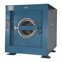
Milnor 48040F7Z Maintenance Manual (86 pages)
Rubber Spring-resting, Non-tilt Washer-extractor
Brand:
Milnor
| Category:
Washer
| Size: 6 MB
Table of Contents
Table of Contents
9
Sections
11
Chapter 1. Machine Description, Identification, and Certification
13
About this Milnor Machine-Rubber Spring-Resting, Non-Tilt Washer-Extractor
13
Functional Description
13
1.2. General Content of the EC-Declaration of Conformity
13
Chapter 2. Safety
15
General Safety Requirements-Vital Information for Management Personnel
15
Laundry Facility
16
Personnel
16
Safety Devices
16
Hazard Information
16
Maintenance
16
Safety Alert Messages-Internal Electrical and Mechanical Hazards
17
Safety Alert Messages-Cylinder and Processing Hazards
17
Safety Alert Messages-Unsafe Conditions
18
Damage and Malfunction Hazards
18
Hazards Resulting from Damaged Mechanical Devices
18
Hazards Resulting from Inoperative Safety Devices
18
Careless Use Hazards
18
Careless Operation Hazards-Vital Information for Operator Personnel (See also Operator Hazards Throughout Manual)
18
Prevent Damage from Chemical Supplies and Chemical Systems
19
Careless Servicing Hazards-Vital Information for Service Personnel (See also Service Hazards Throughout Manuals)
19
How Chemical Supplies Can Cause Damage
20
Dangerous Chemical Supplies and Wash Formulas
20
Incorrect Configurations that Let Chemical Supply Go in the Machine
21
Equipment and Procedures that Can Prevent Damage
22
Use the Chemical Manifold Supplied
22
Put the Chemical Tube Fully below the Machine Inlet
23
Prevent Leaks
23
Close the Line
23
Do Not Let a Vacuum Occur
23
Flush the Chemical Tube with Water
23
How to Show the Maintenance on a Calendar
24
Chapter 3. Routine Maintenance
24
Routine Maintenance-Rubber Spring-Resting, Non-Tilt Washer-Extractor (Document BIUUUM09)
24
Maintenance Summary
25
Guards and Related Components
25
Filters, Screens, and Sensitive Components
26
Fluid Containers
26
Components that Become Worn
27
Bearings and Bushings
27
Motor Grease Schedule
28
Mechanisms and Settings
28
How to Remove Contamination
29
Contamination Types, Cleaning Agents, and Procedures
29
Lubricant Identification and Procedures
30
Grease Gun Procedures
30
Procedures for Bearing Components Connected to a Grease Plate
31
Procedures for Motors
31
Apply Grease
32
Motor Grease Maintenance Conditions
32
Motor Grease Intervals and Quantities
33
How to Examine Belts and Pulleys
34
Maintenance Components — Machines and Controls Group
34
Electric Box and Inverter
35
Chemical Inlet Manifolds for Chemical Pump Systems
36
Soap Chute and Optional 5-Compartment Supply Injector
36
Air Tube for the Water Level Sensor
37
Look Different
37
Water Pressure Regulator for Chemical Flush
37
Compressed Air Inlet Strainers
38
Steam Inlet Strainer
38
How to Examine Compressed Air Mechanisms
39
Self-Purging Air Line Filter to Remove Moisture and Contamination
39
Compressed Air Mechanisms
40
How to Do a Test of Emergency Stop Mechanisms
40
Speed Sensor (Photoeye) on some Machines
40
Grease Ports for Grease-Only Bearing Assembly
41
Maintenance Components — Large Extractors
41
About the Shock Absorbers
42
Grease Ports for Door — Open Pocket Models
42
How to Do a Test of the Mechanical Brake
43
Suspension Components on each Side of Rubber Washer-Extractor
43
Example of Disk Brake
44
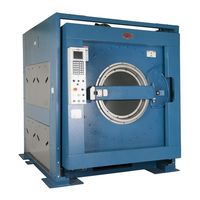
Milnor 48040F7Z Maintenance Manual (42 pages)
Brand:
Milnor
| Category:
Laundry Appliance
| Size: 5 MB
Table of Contents
Table of Contents
8
Machine Description and Identification
11
About this Manual and Your Milnor® Machine
11
Description
11
Machine Identification
11
Machine Data Plate
11
Figure 1 Machine Data Plate
11
Safety
12
Safety - Rigid Washer Extractors
12
Safety Alert Messages-Internal Electrical and Mechanical Hazards
12
Safety Alert Messages-Cylinder and Processing Hazards
12
Safety Alert Messages-Unsafe Conditions
14
Damage and Malfunction Hazards
14
Hazards Resulting from Inoperative Safety Devices
14
Hazards Resulting from Damaged Mechanical Devices
14
Careless Use Hazards
15
Careless Operation Hazards-Vital Information for Operator Personnel (See also Operator Hazards Throughout Manual)
15
Careless Servicing Hazards-Vital Information for Service Personnel (See also Service Hazards Throughout Manuals)
15
Prevent Damage from Chemical Supplies and Chemical Systems
16
How Chemical Supplies Can Cause Damage
16
Dangerous Chemical Supplies and Wash Formulas
16
Incorrect Configuration or Connection of Equipment
16
Figure 2 Incorrect Configurations that Let the Chemical Supply Go in the Ma
17
Equipment and Procedures that Can Prevent Damage
18
Use the Chemical Manifold Supplied
18
Figure 3 Incorrect Configurations that Let the Chemical Supply Go in the Ma
18
Figure 4 Examples of Manifolds for Chemical Tubes. Your Equipment Can Look
18
Close the Line
19
Do Not Let a Vacuum Occur
19
Flush the Chemical Tube with Water
19
Put the Chemical Tube Fully below the Inlet
19
Prevent Leaks
19
Figure 5 a Configuration that Prevents Flow in the Machine When the Pump Is off (if the Chemical Tube and Tank Have no Pressure)
19
Routine Maintenance
20
Maintenance Summary
20
Guards and Related Components
21
Filters, Screens, and Sensitive Components
21
Table 1 Guards and Related Components
21
Table 2 Filters, Screens, and Sensitive Components
21
Fluid Containers
22
Components that Become Worn
22
Bearings and Bushings
22
Table 3 Fluid Containers
22
Table 4 Components that Become Worn
22
Motor Grease Schedule
23
Mechanisms and Settings
23
Table 5 Bearings and Bushings
23
Table 6 Motor Grease Schedule
23
Table 7 Mechanisms and Settings
23
How to Remove Contamination
24
Table 8 Contamination Types, Cleaning Agents, and Procedures
24
Lubricant Identification
25
Table 9 Lubricant Identification
25
Grease Gun Procedures
26
Procedures for Bearing Components Connected to a Grease Plate
26
Procedures for Motors
27
Figure 6 Motor Grease Maintenance Conditions
28
How to Show the Maintenance on a Calendar
29
Table 10 Motor Grease Intervals and Quantities
29
Maintenance Components-Machines and Controls Group
30
How to Examine V-Belts and Pulleys
30
Figure 7 Belt and Pulley Conditions to Look for
30
Table 11 Where to Put Marks on a Calendar
30
Figure 8 How to Adjust Belt Tension on a Machine that Uses Spring Tension
31
Inverters
32
Chemical Devices
32
Figure 9 Electric Box and Inverter. These Are Examples. Your Machine Can Look
32
Water and Steam Devices
33
Figure 10 Chemical Inlet Manifolds for Chemical Pump Systems. See Caution
33
Figure 11 Soap Chute and Optional 5-Compartment Supply Injector. These Are Ex
33
Figure 12 Air Tube for the Water Level Sensor. These Are Examples. Your Ma- Chine Can Look Different
34
Figure 13 Water Pressure Regulator for Chemical Flush. These Are Examples
34
How to Examine Compressed Air Mechanisms
35
Figure 14 Steam Inlet Strainer. These Are Examples. Your Machine Can Look Different
35
Figure 15 Compressed Air Inlet Strainers. These Are Examples. Your Machine Can Look Different
35
Figure 16. Self-Purging Air Line Filter to Remove Moisture and Other Contamination. These Are Examples. Your Machine Can Look Different
36
Figure 17 Compressed Air Mechanisms These Are Examples. Your Machine Can Look Different
37
Photoeyes and Proximity Switches
38
How to Do a Test of Emergency Stop Mechanisms
38
Figure 18 Speed Sensor (Photoeye) on some Machines
38
Maintenance Components-Large Extractors
39
Lubricant Maintenance for Grease-Filled Drive Bearings
39
Figure 19 Grease Ports for Grease-Only Bearing Assembly
39
Lubricant Maintenance for Non-Drive Components
40
How to Do a Test of the Mechanical Brake
40
About the Shock Absorbers
41
Advertisement
Related Products
Milnor 48040F7D
Milnor 48040F7B
Milnor 48040F7J
Milnor 48040F7N
Milnor 48040F7W
Milnor 48040F Series
Milnor 48040F7 Series
Milnor 48040H7W
Milnor 48040H7R
Milnor 48040 Series
Milnor Categories
Washer
Industrial Equipment
Controller
Laundry Appliance
Dryer
More Milnor Manuals
Login
Sign In
OR
Sign in with Facebook
Sign in with Google
Upload manual
Upload from disk
Upload from URL