Sign In
Upload
Manuals
Brands
Millipore Manuals
Test Equipment
Integritest Exacta
Millipore Integritest Exacta Manuals
Manuals and User Guides for Millipore Integritest Exacta. We have
1
Millipore Integritest Exacta manual available for free PDF download: Operating And Maintenance Manual
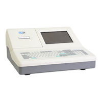
Millipore Integritest Exacta Operating And Maintenance Manual (284 pages)
Brand:
Millipore
| Category:
Test Equipment
| Size: 4 MB
Table of Contents
Table of Contents
4
Using Help for the Integritest Exacta Instrument
8
Getting Started
12
Figure 1: Keyboard
19
Hardware Connections
20
Figure 2: Integritest Instrument (Bottom Rear View)
24
Figure 3: Rear Panel
25
Table 1: Electrical Connections
25
Figure 4: Side Panel
27
Figure 5: Connecting and Disconnecting Exhaust Tubing
28
Figure 6: Inlet and Outlet Tubing Connections
30
Figure 7: Correct Filter Housing Assembly
30
Figure 8: Cutting the Tubing
31
First Log on
32
Chapter Contents
34
Figure 9:Begin Logon Prompt
36
Introduction
36
Control Menu Screen
37
Figure 10: Control Menu Screen, Exacta Tab
37
Check Security Log
38
Clear Security Log
38
Figure 11: Login Failures Report Window
38
Log off Administrator
38
Restart in Archive Mode
38
Restart in Normal Mode
38
Tab 1 - Exacta
38
Stop Instrument
39
Event Log Utility
40
Figure 12: Control Menu Screen, System Admin Tab
40
Tab 2 - System Admin
40
User Registration Utility
40
Automatic Logout Utility
41
Backup Utility
42
Figure 13:Control Menu Screen, Tools Tab
42
Tab 3 - Tools
42
Figure 14: Backup Options Screen
43
Figure 15: Restore Screen
43
Fingerprint Unit Utility
43
Restore Utility
43
Figure 16: Superuser Access Control Screen
44
Printers Utility
44
Superuser Access
44
Figure 17: Windows NT Printer Selection Window
45
Network Utility
45
Reload Menu Utility
45
Figure 18: Windows NT Network Window
46
Figure 19: Date/Time Properties Window
46
Time and Date Utility
46
Figure 20: Regional Settings Properties
47
Fingerprint Unit Utility
47
Regional Settings Utility
47
Starting/Stopping the Instrument
48
Table of Contents
50
Figure 21: Windows NT Logon Screen
52
Starting the Instrument
52
Figure 22: System Startup Screen
53
Figure 23: Login Screen
53
Figure 24: Shut down Screen
55
Instrument Shutdown
55
Procedure
55
Figure 25: Product Registration Card Dialog Screen
56
Product Registration
56
Figure 26: Main Menu Screen
57
Processing Registration Information
57
Security Setup
58
Table of Contents
60
Administrator
62
Procedure
62
Setting up User Accounts
62
Figure 27: User Manager Window
63
Overview of the User Manager
63
Figure 28:New User Dialogue Box
64
To Create a New User Account
64
Figure 29: Group Memberships Window
65
Figure 30: Account Policy Window
66
Managing Account Policy
66
Before You Click OK, Review the Following Guidelines
67
Password Guidelines
67
Table 2: Password Characters
67
Managing User Access
70
Table of Contents
72
Figure 31: User Operations Screen
74
Introduction
74
Modify User Categories
74
Add Users
75
Figure 32: User Access Levels Screen
75
Modify User Category Access Levels
75
Enter a User
76
Figure 33: User Management Screen
76
Delete All Data for an Existing User
77
Instrument Setup
78
Table of Contents
80
General Setup Procedures
82
Setup Options
82
Table 3: Instrument Setup Locations
82
Accessing the Print Setup Screen
83
Figure 34: Main Menu
83
Figure 35: System Utilities Screen
83
Figure 36: Print Setup Screen, Tab F3, Language
84
From the Setup & Calibration Screen
84
Procedure
84
Step 1. Choosing Language
84
Figure 37: Print Setup Screen, Tab F2, Operator Input
85
Procedure
85
Step 2. Configure Operator Input Screen
85
Figure 38: Print Setup Screen, Tab F5, Default Printer
86
Step 3. Choosing the Default Printer
86
Figure 39: Print Setup Screen, Tab F4, Reports
87
Procedure
87
Step 4. Choose a Report Format
87
Accessing the Setup & Calibration Screen
88
Figure 40: Setup & Calibration Screen
88
From the Main Menu
88
From the Print Setup Screen
88
Step 5. Choose Pressure Units
88
Procedure
89
Step 6. Enter Instrument Description
89
Step 7. Use Temperature Compensation
89
Table 4: Temperature Compensation
89
Filter Editor
90
Table of Contents
92
Accessing the Filter Editor Screen
94
Figure 41: Filter Editor Screen, Tab F2, General
94
Introduction
94
Adding a New Filter Specification
95
General Procedure
95
Figure 42: Filter Editor, Tab F3, Filter Size
96
Table 5: Filter Selection Table
96
Figure 43: Filter Editor, Tab F4, Filter Bubble Point Specifications
97
Table 6: Available Tests
97
Table 7: Tab F4, Bubble Point Test Entries
97
Figure 44: Filter Editor, Tab F5, Filter Diffusion Specifications
98
Table 8: Tab F5, Diffusion Test Entries
98
Table 9: Tab F6, Hydrocorr Test Entries
99
Figure 45: Filter Hydrocorr Specifications
100
Modifying an Existing Filter Specification
100
Integritest Exacta Instrument Tests
102
Test Editor
110
Introduction/Accessing the Test Editor Screen
112
Introduction
114
Table 10: Summary of Modifiable Test Editor Fields
114
Test Editor Features
114
Using the Test Editor
114
Accessing the Test Editor Screen
117
Figure 46: Test Details Screen, Tab F2, General
117
Program a New Test
117
Figure 47: Test Details Screen, F3, Options
119
Figure 48: Test Details Screen - F4: Specifications
120
Modify an Existing Test
120
Running a Test
122
Figure 49: Test Selection Screen
126
Figure 50: Operator Input Screen
127
Figure 51: Test Progress: CHECK
128
Table 11: Icon Functions
128
Table 12: Typical Test Times and Values Reported
129
Table 13: Normal Test Cycle Status Messages
129
Printing
132
Table 14: Print Variables
136
Figure 52: Sample Report Printout
138
Printer Maintenance and Troubleshooting
140
Table of Contents
142
Changing the Paper
144
Figure 53: Internal Printer
144
Printer Maintenance and Troubleshooting
144
Figure 54: HP Inkjet Cartridge (Catalogue No. XITXSP105)
145
Priming the HP Printer Cartridge
145
Replacing the Ink Cartridge
145
Connecting an External Printer
146
Procedure
146
Data Management
148
Table of Contents
150
Configurable Operator Input
152
Data Management Features of the Integritest Exacta Instrument
152
Database and Operation Logs
152
Electronic Test Data
152
Filter Database and Filter Editor
152
Test Database and Test Editor
152
Accessing the Manage Test Data Screen
153
Data Management Procedures (Maintenance of Electronic Test Data)
153
Data Search
153
Figure 55: Manage Test Data Screen
153
Simple Query Procedure
153
Advanced Query Procedure
154
Figure 56: Advanced Query Screen1, Date Selection
154
Figure 57: Advanced Query Screen 2, Filter & Test Selection
155
Figure 58: Advanced Query Screen 3, Operator Input Selection
156
Printing Stored Test Data Procedure
156
Figure 59: Print Preview Screen
157
Archiving
158
Figure 60: Database Size Yellow Warning Message
158
Introduction
158
Size Monitor Warning Messages
158
Figure 61: Database Size Red Warning Message
159
Figure 62: Warning Message after Reboot
159
Viewing Archives
159
Figure 63: Archive Selection Menu
160
Figure 64: Archive Confirmation Prompt
161
Restarting in Normal Mode
161
Backing up Data
162
Backup and Restore
162
Complete Backup
162
Current Data Only
162
Files Saved
162
Archived Test Results Only
163
Complete Backup and Audit Files
163
Filter and Test Definitions Only
163
Table 15: Backup File Types
163
Figure 65: Backing up Data to Floppy Diskette
164
Procedure
164
Restoring Data from Backup Disks
164
Figure 66: no Disk Warning
165
Figure 67: Restoring from a Set of Floppy Disks
165
Figure 68: Restore File List
166
Figure 69: Restore Complete Prompt
166
Auditing Files
167
Figure 70: Zipped Audit File
167
Procedure
167
Table 16: Backup File Type Indicators
167
Figure 71: Files Unzipped for Audit
168
Figure 72: Auditor Extraction
169
Figure 73: Auditor File Listing
169
Figure 74: Auditor Extraction Completed
170
Networking
172
Maintenance and Calibration
176
Table of Contents
178
Background/Introduction
180
Calibration Approach
180
Calibration Frequency Recommendations
180
External Calibration
180
Internal Calibration
180
Calibration Adjustment Decisions
181
Calibration Criteria
181
Calibration Curve Fits
181
Pressure Transducer Calibration-External Calibration
181
Table 17: Transducer Specifications
181
Table 18: Calibration Adjustment Decisions (A)
181
Calibration Procedure
182
Calibration Setup
182
Recommended Reference Pressure Gauge
182
Figure 75: Pressure Calibration
183
Calibration Adjustment Decisions
186
Calibration Criteria
186
Calibration Curve Fits
186
Pressure Transducer Calibration-Internal Calibration
186
Table 19: Transducer Specifications
186
Table 20: Calibration Adjustment Decisions (B)
186
Calibration Procedure
187
Calibration Setup
187
Calibration Adjustment Decisions
189
Calibration Criteria
189
Calibration Curve Fits
189
Table 21: Temperature Sensor Specifications
189
Table 22: Calibration Adjustment Decisions (C)
189
Temperature Sensor Calibration
189
Calibration Setup
190
Recommended Reference Temperature Sensor
190
Table 23: Recommended Bath Temperatures
190
Temperature Calibration Procedure
190
Figure 76: Temperature Calibration
191
Internal Leak Testing
194
Leak Test Procedure
194
Leak Test Setup
194
Leak Testing Criteria
194
Figure 77: Setup and Calibration, Tab F5, Leak Testing
195
Figure 78: Leak Test Progress Report
195
Figure 79: Leak Test Report Example
196
Fan Filter Replacement
197
Figure 80: Fan Filter Assembly
197
Procedure
197
Replaceable Parts
197
Routine Maintenance-Replaceable Components
197
Inlet Tubing Gas Filter Replacement
198
Main Fuse Replacement
198
Procedure
198
Troubleshooting
200
Table of Contents
202
General Troubleshooting Procedure
204
Introduction
204
Table 24: Troubleshooting Testing Problems
204
Possible Failure Modes
205
Exacta Gross Leak Criteria
206
Gross Leak Detection During the Diffusion Flowrate Step
206
Gross Leak Detection Prior to Sizing
207
Table 25: Assumed Volume Used for Leak Detection
207
Exacta Gross Leak Troubleshooting Procedure
208
Hardware
208
Instrument
208
Filter
209
Environmental
210
Calibration
211
Diagnostic Tools
211
Figure 81: Diagnostics Screen
211
Hardware Diagnostics
211
Self-Diagnostics
211
Table 26: Diagnostics Screen Component Identification
212
Error Messages
214
Figure 82: Example of an Error Message Box
218
Table 27: Status Error Messages
219
Table 28: General Error Messages
222
Instrument Repair
226
Table 29: Spare Parts and Accessories
231
Warranty
232
Integritest Exacta Specifications
236
Table of Contents
238
Bubble Point Test
240
Diffusion Test
240
Performance Specifications
240
Table 30:Bubble Point Test Performance Specifications
240
Table 31: Diffusion Test Performance Specifications
240
Table 32: Hydrocorr Test Performance Specifications
240
The Hydrocorr Test
240
Computer
241
Dimensions
241
Electrical Specifications
241
Fuse Rating
241
Input and Output Connections
241
Physical Characteristics
241
Table 33: Dimensions
241
Weight
241
Cleaning
242
Operating Environment
242
Ce Approval Characteristics
243
EMC Directive
243
Low-Voltage Directive (Safety)
243
Scope
243
Equipment Maintenance & Safety
244
Figure 83: Warning Label
244
Safety Warnings
244
Figure 84: Caution Label
245
Safety and Electromagnetic Compliance
245
Interface Conventions
246
Table of Contents
248
Data Entry Windows
250
Dialog Boxes
250
Interface Conventions
250
List Boxes
250
Check Boxes
251
Option Buttons and Option Groups
251
Pull-Down Menus
251
History Tables
252
Contacting Millipore
254
Contacting Millipore the U.s
258
Products Ordered in the U.S. for Shipment Overseas
258
Millipore Worldwide
259
Products Ordered in Countries Other than the U.S
259
Contact Our Web Site
261
Table 34: Recommended Hydrocorr Gas Volumes
264
Table 35: Conversion Factors
264
Index
276
Advertisement
Advertisement
Related Products
Millipore ICW-3000
Millipore Exact-Air II
Millipore Categories
Laboratory Equipment
Water Filtration Systems
Water Pump
Dispenser
Test Equipment
More Millipore Manuals
Login
Sign In
OR
Sign in with Facebook
Sign in with Google
Upload manual
Upload from disk
Upload from URL