Sign In
Upload
Manuals
Brands
Miller Manuals
Welding System
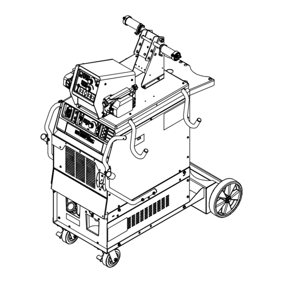
PipeWorx 400 VRD
Miller PipeWorx 400 VRD Manuals
Manuals and User Guides for Miller PipeWorx 400 VRD. We have
1
Miller PipeWorx 400 VRD manual available for free PDF download: Owner's Manual
Miller PipeWorx 400 VRD Owner's Manual (114 pages)
Brand:
Miller
| Category:
Welding System
| Size: 4 MB
Table of Contents
Table of Contents
5
Section 1 − Safety Precautions - Read before Using
7
Symbol Usage
7
Arc Welding Hazards
7
Additional Symbols for Installation, Operation, and Maintenance
9
California Proposition 65 Warnings
10
Principal Safety Standards
10
EMF Information
10
Section 2 − Consignes de Sécurité − Lire Avant Utilisation
11
Symboles Utilisés
11
Dangers Relatifs au Soudage à L'arc
11
Dangers Supplémentaires en Relation Avec L'installation, le Fonctionnement et la Maintenance
13
Proposition Californienne 65 Avertissements
15
Principales Normes de Sécurité
15
Informations Relatives aux CEM
15
Section 3 − Definitions
17
Additional Safety Symbols and Definitions
17
Miscellaneous Symbols and Definitions
20
Section 4 − Specifications
21
Serial Number and Rating Label Location
21
General Specifications
21
MIG Duty Cycle and Overheating
22
Stick and TIG Duty Cycle and Overheating
22
Environmental Specifications
23
Important Information Regarding CE Products (Sold Within the EU)
23
Section 5 − Installation
24
Selecting a Location
24
Remote 14 Accessory Receptacle Information
25
Turning on Remote 14 Receptacle Control for Stick
26
Changing Wire Feed Speed from Inches Per Minute (IPM) to Meters Per Minute (MPM)
27
Remote 14 Wire Feeder Control Receptacle Information
28
Supplementary Protector CB2
29
Volts AC Single Receptacle RC2 and Supplementary Protector
30
Lifting Eye on Power Source
31
Electrical Service Guide
32
Connecting 3-Phase Input Power
34
Installing Optional Handles, Running Gear and Cooler
36
Assembling and Installing Cable Hanger
37
Proper Ring Terminal Connection to Volt Sense Lead
38
Connecting Volt Sense Lead and Work Cable to Clamp
38
Weld Output Terminals and Selecting Cable Sizes* Recommended for Pipeworx 400
39
Connecting Weld Output Cables
40
Typical Connection Diagram for MIG (GMAW) Equipment with Feeder on Power Source
41
Typical Connection Diagram for MIG (GMAW) Equipment with Feeder on Cart
42
Wire Feeder Rear Panel Connections and Rotating Drive Assembly
43
Gun Trigger Receptacle
44
Installing and Threading Welding Wire
45
Voltage Sensing Lead and Work Cable Connections for Multiple Welding Arcs
46
Arranging Welding Cables to Reduce Welding Circuit Inductance
48
Typical Connection Diagram for Stick (SMAW) Equipment
49
Typical Connection Diagram for Two Piece Air-Cooled TIG (GTAW) Torch
50
(Using Gas Solenoid Inside Power Source)
50
Typical Connection Diagram for One Piece Air-Cooled TIG (GTAW) Torch
51
(Using Gas Solenoid Inside Power Source)
51
Typical Connection Diagram for Liquid-Cooled TIG (GTAW) Torch
52
(Using Gas Solenoid Inside Power Source)
52
Section 6 − Operation
53
Operational Terms
53
Welding Power Source Controls
55
Memory Card Slot
56
TIG Sequence Control
61
Stick Process Selection Setup Example
62
TIG Process Selection Setup Example
63
MIG Process Selection Setup Example 1
64
MIG Process Selection Setup Example 2
65
Wire Feeder Controls
66
Preflow and Postflow Adjustment
69
Wire Feeder Left Side Active Setup Example
70
Wire Feeder Right Side Active Setup Example (Dual Feeder Only)
71
Wire Feeder Non-MIG Setup Example
72
Wire Feeder Timed Purge Example
73
Wire Feeder Auto Jog Example
74
Basic Parameters for Pipeworx 400
75
Lift-Arc and HF TIG Start Procedures
78
Section 7 − Maintenance and Troubleshooting
79
Routine Maintenance
79
Blowing out Inside of Unit
79
Restoring Factory Defaults
80
Viewing Software Revision
80
Power Source Calibration Procedure
80
Removing Right Side Panel and Measuring Input Capacitor Voltage
82
Welding Power Source and Feeder Diagnostic Help Codes
83
Troubleshooting Welding Power Source/Wire Feeder Issues
85
Welding Power Source Troubleshooting
86
Wire Feeder Troubleshooting
87
Cooler Troubleshooting
87
Section 8 − Electrical Diagram
88
Section 9 − High Frequency
92
Welding Processes Requiring High Frequency
92
Installation Showing Possible Sources of HF Interference
92
Recommended Installation to Reduce HF Interference
93
Section 10 − Parts List
94
Advertisement
Advertisement
Related Products
Miller Gold Star 400SS
Miller PipeWorx 400
Miller Big Blue 400D
Miller Dynasty 400 CE
Miller Big Blue 400P
Miller DIALARC 400 AC/DC
Miller DELTAWELD 402
Miller Blue Thunder 403
Miller Big Blue 401DX
Miller Invision 456P
Miller Categories
Welding System
Welding Accessories
Camera Accessories
Portable Generator
Motorcycle Accessories
More Miller Manuals
Login
Sign In
OR
Sign in with Facebook
Sign in with Google
Upload manual
Upload from disk
Upload from URL