Sign In
Upload
Manuals
Brands
Microwave Radio Communications Manuals
Modem
SCM4000
Microwave Radio Communications SCM4000 Manuals
Manuals and User Guides for Microwave Radio Communications SCM4000. We have
1
Microwave Radio Communications SCM4000 manual available for free PDF download: Technical Reference Manual
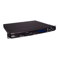
Microwave Radio Communications SCM4000 Technical Reference Manual (275 pages)
Single Carrier Modem
Brand:
Microwave Radio Communications
| Category:
Modem
| Size: 6 MB
Table of Contents
Conventions
4
On-Line Viewing
4
Symbols Used
4
Warranty Information
5
Table of Contents
7
Introduction
11
SCM4000 Demodulator/Decoder
11
Glossary
12
Calling for Service
13
Supported Repairs
13
Product Description
15
System Description
15
Configuration Options
16
Configuration Descriptions
16
SCM4000 Front Panel View
17
Modulator Rear Panel View
17
Demodulator Rear Panel Rear View
17
Modulator/Demodulator Rear View
18
Modulator/Encoder Rear View
18
Demodulator/Decoder Rear View
18
Power Options
19
Mounting and Deployment Options
19
System Integration
19
SCM4000 Configurations
19
SCM4000 Modulator
20
SCM4000 Demodulator
20
SCM4000 Modulator Block Diagram
20
SCM4000 Demodulator Block Diagram
20
SCM4000 Modulator/Demodulator
21
SCM4000 Modulator/Encoder
21
SCM4000 Demodulator/Decoder
22
For more Information
22
Routine Operation
23
SCM4000 Controls and Indicators
23
Overview of Controls, Indicators and Connectors - - -
23
Alert Led
24
Alphanumeric Display
24
Power Led
24
SCM4000 Controls, Indicators, and Connectors
24
SCM4000 Modulator Connectors
25
SCM4000 Demodulator Connectors
26
SCM4000 Modulator/Demodulator Connectors - -
28
SCM4000 Modulator/Encoder Connectors - - - - - -
29
SCM4000 Demodulator/Decoder Connectors- - - -
31
Preparing for Operation
32
SCM4000 Demodulator/Decoder Connectors
32
Using the SCM4000 Screens
33
Fixed or Mobile Installation
33
Powering the SCM4000
33
Main Screen - Typical
33
Overview
34
SCM4000 Modulator Main Screen
34
Using the SCM4000 Menus
34
Top Level Main Menu Hierarchies
35
SCM4000 Demodulator Main Screen
35
SCM4000 Modulator/Demodulator Main Screen
35
SCM4000 Modulator/Encoder Main Screen
35
Main Screen
39
Cursors
39
Preset Menu - Typical
39
Preset Selection
40
Changing Operating Parameters
40
Menu Option Selections
40
Return to the Main Screen
40
Accessing the Menus
41
SCM4000 Main Screen - Typical
41
System Menu - Typical
41
SCM4000 Monitor/Change Operations - - - - - - - - - -
41
SCM4000 Modulator Menu Operations- - - - - - - - - -
42
Monitor/Change Symbol Rate
43
Modulator Menu - Typical
44
Recall Preset Option
44
Monitor/Change Modulation Type
45
Monitor/Change ASI Bit Rate
49
Monitor/Change DS3/E3 Enable
51
Monitor/Change DS3/E3 Line Standard Setting -
53
Monitor/Change Ethernet LIU Bit Rate - - - - - - -
64
Monitor/Change RS232/RS485 Baud Rate - - - -
68
Monitor RS232/RS485 Bit Rate
71
Monitor/Change SMPTE Enable
72
Monitor/Change SMPTE Mode
74
Monitor/Change T1/E1 Line Standard- - - - - - - -
80
Monitor/Change T1/E1 Termination - - - - - - - - -
82
Monitor/Change T1/E1 Line Coding State - - - - -
84
Monitor/Change T1/E1 Receiver Gain - - - - - - -
87
Monitor T1/E1 Bit Rate
89
Monitor/Change if Level
90
Monitor/Change Spectrum Inverter State - - - - -
92
Monitor/Change CW Tone State
94
Monitor/Change PRBS State
96
SCM4000 Demodulator Menu Operations - - - - - - -
98
Monitor/Change Symbol Rate Settings - - - - - - -
99
Monitor/Change Modulation Type Settings
101
Monitor Signal-To-Noise Ratio
102
Monitor/Change ASI Bit Rate Settings - - - - - - -
105
Monitor/Change DS3/E3 Line Standard Setting -
108
Monitor/Change DS3/E3 Line Equalizer Setting-
110
Monitor/Change Ethernet LIU Rate
116
Monitor/Change RS232/RS485 Baud Rate - - - -
119
Monitor/Change T1/E1 Line Standard - - - - - - -
124
Monitor/Change T1/E1 Line Coding - - - - - - - -
126
Monitor/Change T1/E1 Line Build out - - - - - - -
128
MPEG Encoder Menu Options
140
Monitor/Change Color Bars Settings
140
SCM4000 Modulator/Encoder Menu Operations - -
140
Monitor/Change Audio a Settings
150
Monitor/Change Color Bars Settings - - - - - - - -
158
MPEG Decoder Menu Options
158
Monitor/Change Audio Output Settings - - - - - -
160
Monitor/Change Generator Lock Settings - - - -
161
Monitor/Change NTSC Pedestal Settings - - - -
163
Monitor/Change BISS Settings
165
Monitor Video Status
170
Monitor Packet Errors
171
Monitor Service Name
173
SCM4000 System Menu Operations
174
Monitor/Change Active Preset
175
Save Preset Settings
176
Recall Preset Settings
177
Monitor Active Errors
178
Monitor/Clear Error Log
179
Monitor System Information
180
Perform System Reset
182
Modulator Settings Menu Map - Top Level
183
Modulator Settings Menu Maps
184
Demodulator Settings Menu Map - Top Level
186
Demodulator Settings Menu Maps
187
MPEG Encoder Settings Menu Map
188
System Menu Map
190
Troubleshooting
191
Troubleshooting
191
Status Leds
191
Status LED Indications
191
Error Codes
192
SCM4000 Modulator Primary Error Codes
193
SCM4000 Demodulator Primary Error Codes
195
SCM4000 Encoder Parameter Errors
198
SCM4000 Decoder Parameter Errors
198
Operational Problems
201
Video Problems
201
Link Setup Guide
205
Installation
207
Unpacking
207
Initial Inspection
207
Damage in Shipment
207
Installing the SCM4000
208
Equipment Rack
208
Mounting the SCM4000
208
Ventilation
209
Moisture
209
Cabling
209
MRX4000 Mounting
209
Power Connections
210
Power Requirements
210
Power Supply and Distribution
210
AC Input Power Connector
210
Grounding
211
Panel Power Connections
211
DC Input Power Connector
211
Audio Connections
212
Panel Connections
212
Modulator/Encoder Rear Panel
212
AUDIO a and B Connector Pin-Outs
213
Encoder AUDIO a and B Pin-Out Connections
213
Decoder AUDIO a and B Pin-Out Connections
213
Signal Connections
214
Audio Inputs and Outputs
214
Audio Configurations
214
Modulator Rear Panel Connectors
214
Demodulator Rear Panel Connectors
215
Modulator/Demodulator Rear Panel Connectors
215
Modulator/Encoder Rear Panel Connectors
216
Demodulator/Decoder Rear Panel Connectors
216
SCM4000 Configuration Block Diagrams
217
Modulator Block Diagram
217
Demodulator Block Diagram
217
Modulator/Demodulator Block Diagram
218
Modulator/Encoder Block Diagram
218
Modulator Simplex Transmit Site Block Diagram - Typical
219
Demodulator Simplex Receive Site Block Diagram - Typical
220
Modulator/Encoder Simplex Transmit Site Block Diagram - Typical
222
Front Panel RS-232 Connector
224
SCM4000 Rear Panel Connectors
224
RJ-45 Connector Pin-Outs
227
RJ-45 T1/E1 Connector Pin-Outs
227
RJ-45 10/100 Ethernet Connector Pin-Outs
227
Cable Assemblies
228
RS-232 Connector Pin-Outs
228
RS-485 Connector Pin-Outs
228
SUM ALARM Connector Pin-Outs
228
Alarm Harness
229
DB-9 to DB-25 Wiring Harness
230
DB-9 to XLR Wiring Harness
231
Powering up
232
Product Modifications
232
Checks before Power-Up
232
Initial Power-Up
232
Repair
233
Replacement Parts
235
External Cables
235
Power Fuses
235
Power Fuse Location = DC Power Option
235
Theory of Operation
237
System Architecture
237
Operation
238
Interfaces
238
Data Mux
238
SCM4000 Modulator Description
239
SCM4000 Demodulator Description
240
Glossary
243
A-1: Useful Terms
243
Preset Settings
251
B-1: Modulator Preset Settings Menu - Top Level Worksheet
252
MPEG Encoder Settings Menu Map Worksheet
257
Symbol Rate Calculations
259
Appendix Overview
259
Bit Rates and Symbol Rates
259
Bit Rate Calculations - Example
260
Modulation Vs. Symbol Rates - Valid Rate Example
261
Modulation Vs. Symbol Rates - Invalid Rate Example
261
Bit Rate Calculation Worksheet
265
Index
267
Appendix Overview
259
Advertisement
Advertisement
Related Products
Microwave Radio Communications Strata
Microwave Radio Communications Categories
Receiver
Modem
Antenna
Transmitter
More Microwave Radio Communications Manuals
Login
Sign In
OR
Sign in with Facebook
Sign in with Google
Upload manual
Upload from disk
Upload from URL