Sign In
Upload
Manuals
Brands
Michco Manuals
Floor Machine
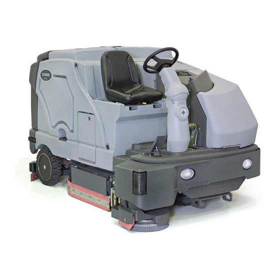
sc8000
Michco sc8000 Manuals
Manuals and User Guides for Michco sc8000. We have
1
Michco sc8000 manual available for free PDF download: Service Manual
Michco sc8000 Service Manual (225 pages)
Brand:
Michco
| Category:
Floor Machine
| Size: 22 MB
Table of Contents
Service Manual
2
Table of Contents
3
General Information
9
General Machine Description
9
Service Manual Purpose and Application
9
Revision History
9
Other Reference Manuals and Information Sources
9
Nilfisk-Advance Publications
9
Engine Manufacturers' Technical Manuals
10
Diagnostic and Service Tools
10
Conventions
12
Parts and Service
12
Nameplates
12
Cautions and Warning Symbols
13
General Safety Instructions
13
Jacking the Machine
15
Transporting the Machine
15
Towing the Machine
16
Technical Specifications
17
General Machine Dimensions and Capacities
17
Overall Dimensions
18
Engine and Machine Performance
19
Fastener Torque Specifications
19
Maintenance
19
Maintenance Schedule
19
Recommended Service Materials
20
Daily Maintenance
20
Maintenance Every 15 to 20 Hours
21
Monthly Maintenance
21
Maintenance Every 150 Hours
21
Maintenance Every 400 Hours
22
Maintenance Every 800 to 1000 Hours
22
Maintenance Every 2000 Hours
22
Lubrication Points
23
PM Check List - SC8000
24
General Machine Overview
27
Major Machine Components
27
Control Panel Switches
29
Control Panel Indicators
31
Liquid Crystal Display (LCD)
33
General Displays
33
Attention and Warning Displays
33
Chassis System
36
Major Chassis Components
36
Control System
38
Functional Description
38
Overview
38
Control System Wiring Diagram
38
Circuit Description
38
Component Locations
39
Control Board (Driver Box) Connectors
40
J1 Main Control Board Connectors
40
J2 Main Control Board Connectors
41
J3 Main Control Board Connectors
42
Control Board (Driver Box) Programming Options
43
Foot Pedal Neutral Position and Deadband Adjustment
43
Configuration Display Menu
44
User Options Menu
46
Configuration Menu
50
Operator Presence Control (OPC)
53
Troubleshooting
54
Main Control Board Fault Codes
54
Systems Disabled by Faults
58
Electrical System
60
Functional Description
60
Overview
60
Power Supplies
60
Circuit Description
60
Component Locations
61
K1 Power Relay
61
Circuit Breakers
61
100-Amp Fuse F1
62
Troubleshooting
62
Specifications
64
Component Specifications
64
Connector Callout - Relay PCB
64
Input/Output Table
65
Shop Measurements - Driver Box
71
Shop Measurements - Relay PCB
78
Wiring Diagram - 56108185 Rev. a Sheet 1 Kubota LPG Engine
79
Wiring Diagram - 56108185 Rev. a Sheet 2 Kubota Diesel Engine
80
Wiring Diagram Kubota 1.6L LPG Engine 56107659 REV. a
81
Wiring Harness Schematic, Machine - 56108186 REV a Sheet 1 of 2
82
Wiring Harness Schematic, Engine Interface and Kubota Diesel - 56108186 REV a Sheet 2 of 2
83
Engine System, Diesel
84
Functional Description
84
Overview
84
Diesel Engine Starter Circuit Diagram
84
Circuit Description
85
Component Locations
86
Maintenance and Adjustments
87
Engine Coolant
87
Engine Oil
87
Engine Air Filter Maintenance
89
Troubleshooting
89
General Troubleshooting
89
Engine Overheating Problems
89
Loss of Oil Pressure Protection
90
Engine will Not Crank - Start Inhibit Active
90
Engine Stops Running - Run Inhibitactive
90
Diesel Engine will Not Run at High Speed or Turbo Speed
91
Troubleshooting the Kubota Engine Speed Governing System
92
Specifications
93
Engine Specifications
93
Connector Callout - Relay PCB
94
Special Tools
94
Engine System, LPG
95
Functional Description
95
Kubota 1 6L LPG Fuel System Description
95
Engine Start and Run Circuit Description
96
Circuit Description
96
Engine Protection - Low Oil Pressure Shutdown
97
Engine Protection - High Temperature
97
Engine Speed Control
97
Component Locations
98
LPG Electrical Components
98
Maintenance and Adjustments
101
Maintenance Schedule
101
Engine Oil
102
Engine Coolant
102
Engine Air Filter Maintenance
104
Troubleshooting
104
General Troubleshooting
104
Engine Overheating Problems
105
Shop Measurements
107
Special Tools
108
Hydraulic System
109
Functional Description
109
Overview
109
Electrical Schematic
110
Electrical Circuit Description
110
Hydraulic Schematic
111
Component Locations
112
Major Components
112
Hydraulic Cylinders
113
Hydraulic Motors
113
Hydraulic Pumps
114
Hydraulic Valve Block/Manifold
114
Hydraulic Manifold Assembly Component Location Key
117
Maintenance and Adjustments
118
Hydraulic Oil
118
Hydraulic Oil Filter
118
Troubleshooting
119
General Troubleshooting
119
General Information Regarding Checking Hydraulic Pressures
119
Test Port Nominal Pressure Readings
119
Specifications
121
Special Tools
124
Options and Accessories
125
Recovery System
131
Functional Description
131
System Overview
131
Recovery System Wiring Diagram
131
Electrical Circuit Description
132
Recovery System Hydraulic Diagram
132
Component Locations
134
Recovery Tank
134
Daily Maintenance
135
Troubleshooting
135
Removal and Installation
136
Recovery Tank
136
Specifications
138
Special Tools
138
Scrub System, Cylindrical
139
Functional Description
139
Overview
139
Cylindrical Scrub System Wiring Diagram
139
Circuit Description
139
Cylindrical Scrub System Hydraulic Diagrams
141
Component Locations
144
Troubleshooting
145
General Troubleshooting
145
Main Scrub Deck and Right Side Scrub down
147
Main Scrub Deck and Right Side Scrub Pressure
148
Main Scrub and Side Sweep/Scrub on
149
Specifications
150
General Specifications
150
Scrub Pressures
150
Special Tools
151
Scrub System, Right Side
152
Functional Description
152
Overview
152
Right Side Scrub System Wiring Diagram
152
Circuit Description
152
Right Side Scrub System Hydraulic Diagrams
153
Component Locations
155
Maintenance and Adjustments
157
Side Brush Tilt Adjustment
157
Troubleshooting
158
General Troubleshooting
158
Main Scrub Deck and Right Side Scrub down
159
Main Scrub and Side Sweep/Scrub on
160
Specifications
161
Special Tools
161
Solution System
162
Functional Description
162
Overview
162
Solution Flow Control
162
Detergent System
163
Extended Scrub System
164
Right Side Scrub Brush
165
Wash Hose
165
Dustguard ™ Spray Nozzles
166
Solution System Wiring Diagram
166
Circuit Descriptions
167
Component Locations
173
Maintenance and Adjustments
175
To Clean the Solution Filter Screen
175
To Adjust the Dustguard™ Spray Nozzles
176
To Clean the Dustguard™ Spray Nozzles
176
To Clean the Extended Scrub System Strainer
176
To Clean the Solution Delivery Trough
176
Detergent System Maintenance
177
Troubleshooting
180
General Troubleshooting
180
Main and Right Side Solution Valves and Solution Pump
183
Specifications
184
Component Specifications
184
Solution and Detergent Delivery Rates
185
Squeegee System
186
Functional Description
186
Overview
186
Squeegee System Wiring Diagram
186
Circuit Description
186
Squeegee System Hydraulic Diagrams
187
Component Locations
189
Troubleshooting
190
General Troubleshooting
190
Vacuum Fan on and Squeegee down
191
Vacuum Fan off and Squeegee up
192
Specifications
193
Steering System
194
Functional Description
194
Overview
194
Hydraulic Diagrams
195
Component Locations
196
Steering Unit
196
Steer Cylinder
197
Troubleshooting
198
Removal and Installation
198
Specifications
198
Sweep System, Side Broom
199
Functional Description
199
Overview
199
Side Broom Sweep System Wiring Diagram
199
Circuit Description
199
Side Broom Sweep System Hydraulic Diagrams
200
Component Locations
202
Single (Left-Hand) Sweep
202
Dual Sweep
203
Maintenance and Adjustments
204
To Adjust the Side Broom Lift Actuator Motor
204
Troubleshooting
206
General Troubleshooting
206
Main Scrub and Side Sweep/Scrub on
207
Specifications
208
Wheel System, Non-Traction
209
Functional Description
209
Maintenance and Adjustments
210
Brake Tension Adjustment
210
Troubleshooting
211
Specifications
211
Wheel System, Traction
212
Functional Description
212
Overview
212
Piston Pump
212
Foot Pedal, Hydroback and Rotary Sensor
212
Traction Drive Motor
213
Electrical Schematic
213
Electrical Circuit Description
214
Hydraulic Diagrams
214
Component Locations
216
Piston Pump, Hydroback and Rotary Sensor
216
Traction Drive Motor
216
Maintenance and Adjustments
217
Foot Pedal/Hydroback Neutral Adjustment
217
Foot Pedal Neutral Deadband Adjustment
218
Troubleshooting
219
Removal and Installation
220
Push/Pull Control Cable Replacement
220
Hydroback Replacement
222
Traction Drive Motor Hose Routing
223
Specifications
224
Component Specifications
224
Wheel Drive System Torque Specifications
225
Advertisement
Advertisement
Related Products
Michco SD 4317
Michco SD 5120
Michco Categories
Dryer
Vacuum Cleaner
Scrubber
Floor Machine
Water Pump
More Michco Manuals
Login
Sign In
OR
Sign in with Facebook
Sign in with Google
Upload manual
Upload from disk
Upload from URL