Sign In
Upload
Manuals
Brands
MG Manuals
Automobile
MGB
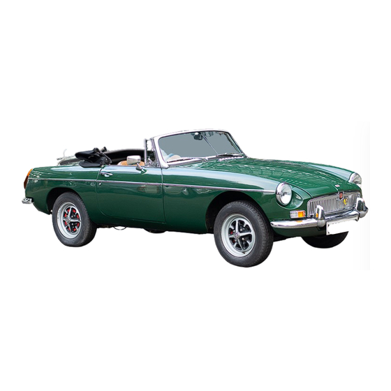
MG MGB Classic Sports Car Manuals
Manuals and User Guides for MG MGB Classic Sports Car. We have
1
MG MGB Classic Sports Car manual available for free PDF download: Workshop Manual
MG MGB Workshop Manual (418 pages)
Brand:
MG
| Category:
Automobile
| Size: 28 MB
Table of Contents
Contents
2
General Data
9
18G, 18Ga
9
18Gb
18
The Engine
36
Table of Contents
36
General Description
38
Oil Pressure
38
Lubrication
38
Engine Oil Filter
38
Oil Pressure Relief Valve
39
Water Pump
39
Rocker Assembly
39
Manifolds
39
Cylinder Head Assembly
40
Refitting Rocker Bushes
40
The Cylinder Head Components
41
Key to the Cylinder Head Components
42
Valve Gear and Valves
43
Refitting the Cylinder Head
43
Removing and Replacing Valves
43
Removing and Replacing Valve Guides
43
Grinding and Testing Valves and Seatings
44
Checking Valve Timing
44
Adjusting Valve Rocker Clearances
44
The Cylinder Block Components
45
Tappets
47
Decarbonizing
47
Timing Chain Cover
48
Timing Chain
48
Timing Chain Tensioner
49
The Chain Tensioner Components
49
Sump and Strainer
50
Oil Pump
50
Main and Big-End Bearings
51
Big—End Bearings
51
Main Bearings
51
Pistons and Connecting Rods
52
Pistons and Gudgeon Pins (18G/18GA)
52
Piston Rings
52
The Engine Internal Components
53
Examination
55
Piston Sizes and Cylinder Bored
55
Checking the Piston Ring to Groove Clearance
55
Checking a Piston Ring Gap
55
Renewing the Camshaft Bearings
56
Removing the Front and Rear Liners
56
Removing the Centre Liner
56
Replacing the Front and Rear Liners
56
Replacing the Centre Liner
57
Reaming the Liners
57
Reaming the Centre Liner
57
Reaming the Front and Rear Liners
57
Removing and Replacing the Crankshaft
58
Removing and Replacing the Flywheel
58
Fitting Flywheel Starter Rings
58
Removing and Refitting the Engine and Power Unit
58
The Engine Mountings
59
Key to the Engine Mountings
60
Engine Controls
61
Removing the Power Unit
61
Exhaust System
62
Closed-Circuit Breathing System
62
Distributor Driving Spindle
63
Piston and Connecting Rod
63
Pistons and Connecting Rods
64
18Gb
64
Press Fit Gudgeon Pin
64
Valve Seat Inserts
67
Ignition Timing Indicator
67
Valve Seat Machining Dimensions
67
Valve Gear
68
Front Cover and Oil Seal
68
Later Engines
68
Single Valve Spring
68
Timing Chain and Tensioner
69
Timing Chain Tensioner Assembly
70
Engine Restraint
72
The Ignition System
73
Distributor
74
Cam Bearing
74
Cam
74
Automatic Timing Control
74
Servicing the Distributor
75
Contact Breaker Points
75
Vacuum Advance
75
Centrifugal Advance
75
Removing and Replacing the Distributor
76
Dismantling the Distributor
76
The Distributor Components
76
Examining the Distributor
77
Assembling the Distributor
77
Static Ignition Timing
77
Tassembling
77
Texamining
77
High-Tension Cables
78
The Vernier Adjustment Nut
78
The Correct Method of Connecting High-Tension Leads
78
Ignition Coil
78
Sparking Plugs
79
Locating the Cause of Uneven Firing
79
Testing the Low-Tension Circuit
79
Locating a Low-Tension Circuit Fault
80
Renewing Contact Breaker Points
80
Removing a Contact Breaker Set—Lucas 45D4
80
Contact Breaker Gap—Checking—Adjusting
81
Distributor Cap
81
Distributor Dwell Angle
81
Refitting the Drive Dog (Lucas Type 45D4)
82
Refitting the Base Plate (Early Cars)(Lucas Type 45D4)
82
The Cooling System
84
Thermostat
88
Temperature Gauge
88
Draining, Flushing and Refilling the Cooling System
88
Removing the Filler Cap
88
The Fan and Water Pump Component
89
Key to the Fan and Water Pump Components
90
Fan Belt
91
Radiator and Diaphragm
91
Filling the Cooling System
91
Cold Weather Precautions
93
Pump with Later-Type Seal,Thrower Deleted
93
Draining and Refilling the Cooling System
94
Radiator
94
Fan Motor
94
Fan Motor Test
95
Radiator Fan Motor Components
95
The Fuel System
97
The auf 300 and HP Fuel Pump Components
99
Body and Valves
100
Type HP
100
Pedestal and Rocker
101
Diaphragm Assembly
101
Body Components
101
Contact Blade
103
Contact Gap Settings
103
Modified Rocker Assemblies
103
Earlier-Type Rocker Assemblies
103
Priming
104
Air Leak Check
104
Valve Seat Check
104
Delivery Check
104
Faulty Diaphragm Action
105
Noisy Pump
105
Pump Operates Without Delivering Fuel
105
The Carburetor Components
106
Key to the Carburetor Components
107
Carbuterrors
108
Slow-Running Adjustments and Synchronization
108
Checking the Nylon Float Level
108
Jet-Centring
109
Float-Chamber
109
Float-Chamber Flooding
109
Float Needle Sticking
109
Air Cleaners
110
Needles
110
Piston Sticking
110
Filter Replacement
110
Carburetter Tuning (S.U. HIF4)
111
Carburetter Installation (S.U. HIF4)
112
Suction Chamber Timing Check (S.U. H11)
113
The S.U. Type HIF Carburetter Components
114
Throttle Pedal
116
Throttle Cable
116
Fuel Pump
116
Fuel Tank
118
Vapour Separator Tank
118
Leak Testing
118
The Clutch
119
The Clutch Components
120
Clutch Assembly
121
A Section through the Clutch
121
Servicing the Clutch
122
Master Cylinder
122
Tolerances
122
Condition of Clutch Facings in Service
122
Slave Cylinder
123
The Clutch Control Components
124
Key to the Clutch Control Components
125
Bleeding the Clutch System
126
Bleeding the Clutch Hydraulic System at the Slavecylinder
126
The Gearbox
127
The Gearbox Components
128
Key to the Gearbox Components
129
Removing the Gearbox
130
Dismantling the Gearbox
130
Dismantling and Assembling the Control Timer
131
Dismantling and Assembling the Rear Extension
131
Dismantling and Assembling the First Motion Shaft
132
Dismantling and Assembling the Laygear
132
Dismantling the Third Motion Shaft
132
Examination of Components
132
Assembling the Third Motion Shaft
133
Assembling the Gearbox
133
Fitting Replacement Bushes
134
Reverse Gear
134
Clutch Withdrawal Fork
134
Fitting the Gearbox Front Cover
135
Third Motion Shaft Bushes
135
The Overdrive
136
The Overdrive Components
137
Key to the Overdrive Components
138
Direct Drive
139
Overdrive Engaged
139
Guide to Service Diagnosis
140
Hydraulic System—Direct Drive
140
Hydraulic System —Overdrive
140
Pump Non-Return Valve
142
Relief Valve
142
Hydraulic Lever Setting
142
Overdrive Does Not Release
142
Operating Valve
143
Testing Oil Pressure
143
Reassembling the Unit
144
Drive Shaft Bearings and Seal
146
Overdrive Relay System
146
Cable Colour Code
146
Gearbox Assembly
148
Rear Extension
148
Front Cover
149
Selector Rods and Forks
150
First Motion Shaft
150
Reverse Idler Gear
150
Third Motion Shaft
151
Fault Diagnosis
161
Overdrive Does Not Engage
161
Overdrive Does Not Disengage
161
Overdrive Slips When Engaged
161
Filters
162
Relief and Low Pressure Valve
162
Solenoid Valve
162
Pump and Non-Return Valve
163
Overdrive Assembly
163
Overdrive Unit
163
Overdrive Adaptor
163
Using the Bridge-Pieces to Remove the Thrust Rods
164
Fitting the Rear Bearing Using Tool 18G 186
164
The
164
Fitting the Rear Oil Sealusing Tool 18G 177
166
Using Tool 18G 185 to Align the Splines
166
The Automatic Gearbox
168
Selector
178
The Selector Rod Adjuster
178
Dipstick and Filler Tube
178
Road Test Procedure
179
Topping up Fluid
179
Refilling after Draining
179
Towing for Recovery
179
Converter Fault Diagnosis
180
Stall Test
180
Air Pressure Test
183
Down-Shift and Throttle Valve Cable
183
Front Clutch and Governor Feed
183
Front Brake Band
183
Transmission Assembly
184
Torque Converter
184
Governor Assembly and Speedometer Drive
184
Rear Clutch
184
Valve Bodies Assembly
185
Governor and Speedometer Drive Gear
185
The Governor Components
185
The Valve Bodies Separated
186
The Check Valves in the Lower Valve Body
186
Location of the Oil Tubes
186
The Lower Valve Body
187
Location of the Pump and Converter Oil Tubes
187
Front Servo
188
Rear Servo
188
The Upper Valve Body
188
Pump
189
Withdrawing the Pump Assembly
189
Using Tool 18G 674 to Check the Gear Train End-Float
189
Front Clutch
190
Fitting Order for the Thrust Washer Sand Front Clutch
191
The Rear Clutch Components
191
Centre Support and Planet Gears
192
Forward Sun Gear Components
192
Using Tool 18G 702 to Refit the Rear Clutch Piston
192
Fitting the Rear Clutch and Forward Sun Gear
192
Driven Shaft and Ring Gear
193
The Gear Train Components
193
The Drive Shaft
193
Manual Valve Shaft and Lever
194
The Propeller Shaft
195
The Propeller Shaft Components
196
Key to the Propeller Shaft Components
197
Removing and Replacing the Propeller Shaft
198
Dismantling the Propeller Shaft
198
Examining the Propeller Shaft
199
Assembling the Propeller Shaft
199
Propeller Shaft - Sealed Type
200
The Rear Axle and Suspension
201
The Rear Axle Components
202
Key to the Rear Axle Components
203
Removing and Replacing a Brake-Drum and Axle Shaft
204
Removing and Replacing a Hub
204
Renewing the Pinion Oil Seal
205
Removing the Differential Pinions
205
Replacing the Differential Pinions
205
Dismantling the Crown Wheel and Pinion
206
Assembling and Setting the Crown Wheel and Pinion
206
Setting the Pinion Position
206
Adjusting Pinion Bearing Preload
208
Setting the Crown Wheel Position
208
Table of Washer and Shim Thicknesses
208
Removing and Refitting the Axle
210
Crown Wheel and Pinion Markings
210
Measuring the Crown Wheel Backlash
210
Rear Road Springs
211
Dismantling and Assembling a Rear Spring
211
To Refit a Rear Spring
211
The Rear Suspension Components
212
Key to the Rear Suspension Components
213
The Rear Axle and Rear Suspension
214
Axle Unit
215
Hub and Axle Shaft
215
Pinion Bearing Preload
219
Available Washers for Pinion Position
219
Available Spacers for Differential Assembly
220
Adjusting the Backlash
221
Road Springs
221
Rear Anti-Roll Bar Components
222
Rear Anti-Roll Bar Locator Dimension
223
The Steering Gear
224
The Steering Gear Components
225
Key to the Steering Gear Components
226
Front Wheel Alignment
227
Steering Wheel
227
Steering Column
227
Steering Column Universal Joint
228
Steering Gear
228
The Assembly of a Tie-Rod Ball Joint
228
Rack and Pinion
229
Examining for Wear
229
Steering Column Alignment
230
Steering Lock Ignition Switch
230
Nylon-Seated Ball Joints
230
Steering Lock and Ignition Starter Switch
231
Rack Assembly
233
Steering Alignment
234
The Front Suspension
235
Front Hubs
236
Removing a Hub
236
Coil Spring
237
Swivel Axles
237
Refitting a Hub
237
The Front Suspension Cross-Member and the Suspension Units
237
The Front Suspension Components
238
Key to the Front Suspension Components
239
Removing and Refitting Bushes
240
Front Suspension Unit
240
Swivel Axle Bushes
240
Additional Swivel Pin Graease Nipple
241
Anti-Roll Bar Components
242
Anti-Roll Bar
243
Front Anti-Roll Bar Components
243
Front Anti-Roll Bar Locator Dimension
244
Hydraulic Dampers
245
The Rear Hydraulic Damper
246
Maintenance
247
Removing and Replacing the Dampers
247
Testing the Dampers
247
The Braking System
249
Brake Pedal
250
Brake Adjustment
250
Hand Brake
251
Bleeding the Brake System
251
The Brake Master Cylinder
252
Disc Brake Units
253
Removing a Calliper Unit
253
Removing the Disc Friction Pads
253
Friction Pad Retaining Pins and Bleed Screw Location
253
The Disc Brake Components
254
Removing the Calliper Pistons
255
A Disc Brake in Section
255
Brake Discs
256
Flexible Hoses
256
Rear Brake Assembly
256
The Rear Brake Components
257
Relining the Brake-Shoes
258
Rear Brake Backplate
258
Servo Unit
259
The Air Valve Assembly Components and Piston
259
Servo Cylinder Assembly
260
Slave Cylinder Assembly
260
Vacuum Servo Components
261
Air Valve Assembly
262
Pedal Free Movement
265
Tandem Master Cylinder
265
Pressure Failure Switch Assembly
266
A Section through the Master Cylinder
266
The Electrical System
268
Battery
269
Fast Charging
269
Adjustments in the Vehicle
269
Preparing Dry-Charged Batteries for Service
270
Preparing New Unfilled, Unchanged Batteries for Service
270
Recharging from an External Source
270
Putting into Use
270
Dynamo
271
Initial Charge
271
Testing on Vehicle When Dynamo Is Not Charging
271
The C40/1 Type Dynamo
272
Brushes
272
Commutator
272
Field Coils
273
Armature
273
Bearings
273
Fitting the Commutator End Bracket
273
Control Box Model RB340
274
Expanding the Pole-Shoesin the Yoke
274
Preliminary Checking of Charging Circuit
275
Cut-Out Relay
275
Cut-In Adjustment
275
Voltage Regulator (Open Circuit)
275
Starter
276
Current Regulator
276
Adjustment of Air Gap Settings
276
Cleaning Contacts
276
The Starter Motor Components
277
Key to the Starter Motor Components
278
Examination of Commutator and Brush Gear
279
Drive
279
Windshield Wiper
281
Wiper Takes no Current
281
Regulator and Fuse Block
281
Resetting the Limit Switch
281
Wiper Takes Abnormally Low Current
282
Wiper Takes Abnormally High Current
282
Removing the Motor, Gearbox, and Wheelboxes
282
Wiper Arm Fixing Details
282
The Windshield Wiper Components
283
Key to the Windshield Wiper Components
284
Armature Bearings
285
Dismantling the Motor
285
Dismantling the Gearbox Unit
285
Light Unit Retaining Screws
285
Headlamps
286
Removing a Light Unit
286
Bulb Replacement
286
Refitting a Light Unit
286
Side and Direction Indicator Lamps
287
Tail and Stop and Direction Indicator Lamps
287
Number-Plate Lamps
287
Panel, Map and Warning Lights
287
Horn
288
Flasher Unit
288
Removing the Horn
288
A Rear Number-Plate Lamp (Early Cars)
288
The Switches
289
Key to the Switches
290
Switches
291
Location and Remedy of Faults
291
Functions of Warning Lamp
291
Checking Faulty Operation
291
Charging Circuit
292
Starter Motor
292
Lighting Circuit
292
Bi-Metal Resistance Instrumentation
292
Battery Voltage
293
Wiring
293
Voltage Stabilizer
293
Gauges
293
Electrically Heated Back Light
294
Cigar Lighter
294
Charging System
294
Alternator
295
The 16AC Alternator Components
295
16AC Alternator Outpu Test Circuit
295
Slip - Rings
297
Rotor
297
Stator
297
Diodes
297
Testing in Position
298
Charging Circuit Resistance Test
298
Removing the Regulator
298
Windshield Wipers - Two Speed
299
Motor and Gearbox Assembly
299
Wheelboxes
299
The Two-Speed Windshield Wiper Motor Components
299
Brush Gear
301
Commutator End Bracket
302
Drive Clutch
302
Light Running Test
303
Torque Test
303
Heater, Wiper and Lighting Switches
303
Console Switches
303
Ignition Switch
304
Direction Indicator/Headlight Flasher/Low-High Beam Switch
304
The Starter Motor—Lucas Type 2M100 Pre-Engaged
305
Starter Motor Relay
306
Solenoid - Coil
306
Solenoid Contacts
306
Brake Warning Switch
307
Light Switch
307
Ignition Starter Switch and Steering Lock
307
Fascia Switches
307
Panel Lamp Rheostat Switch
308
Direction Indicator/Main Beam/Horn Control Switch
308
Instruments and Switches
311
Tachometer
311
Oil Pressure Gauge
311
Speedometer
311
Windshield Wiper/Washer and Overdrive Switch
312
Direction Indicator; Horn and Headlamp Flasher Switch
312
Hazard Warning Switch
312
Map Light Switch
312
Windshield Washer Motor
313
Lamps
313
Hazard Warning Flasher Unit and Audible Warning Buzzer
313
Switches, Warning Lamps and Controls
313
Heater Blower Switch
314
Seat Belt Warning Lamp
314
Hazard Warning Lamp
314
Temperature Rotary Control
314
Air Flow Rotary Control
315
Lighting Switch
315
Seat Belt Warning Lamp and Buzzer - Seat Belt Switch
316
Seat Belt Warning Lamp and Buzzer - Gearbox Switch
316
Sequential Seat Belt System Control Unit
316
Sequential Seat Belt System Circuit Wiring Diagram
318
Cable Color Code
318
Wiring Diagrams
321
Key to the Wiring Diagrams
322
The Wheels and Tyres
342
Jacking up the Gear
343
Tyre Replacement
343
The Side-Lift Jack
343
Removing the Hub Cap (Disc Wheels)
343
Removing and Replacing Road Wheels
344
Valves
344
Tyre Removal
344
Inspection of Wheels and Tyres
344
Repair of Tyres and Tubes
345
Fitting Tyres and Tubes
345
Wire Wheels
345
Tyres
345
Wheel and Tyre Balance
346
Factors Affecting Tyre Life
346
Balancemarks on Tyre and Tube
346
Effect of Temperature
347
Climatic Conditions
347
Road Surface
347
Impact Fractures
347
High-Speed Tyre Pressure Conditions
348
The Body
350
Front Grille
351
Bonnet and Bonnet Lock
351
Windscreen
351
A Section through a Windscreen Pillar
351
Door Trim Pad
352
Door Glass
352
The Door Assembly(Early Tourer Models)
352
Door Glass Regulators
353
Window Regulators and Interior Door Handles
353
Strikes
353
Door Locks
353
Door Lock Remote Control Unit
354
Outer Door Handles
354
Private Lock
354
Seats
355
Luggage Compartment Lock
355
Luggage Compartment Lid
355
Rear Quarter-Light
355
Windscreen and Back-Light Glasses
356
Fascia Panel, Instruments and Controls
356
Body Alignment
357
Paint Refinishing Instructions
359
The Door Components
363
Key to the Door Components
364
The Window Components
365
Key to the Window Components
366
The Fascia Panel Components
367
Key to the Fascia Panel Components
368
The Heater Components
369
Key to the Heater Components
370
Bodywork
371
Bumpers
371
Coachwork
371
Carpets
371
Eelctrically Heated Back-Light
372
Seat Belts
372
Rear Wheel Arch
372
Drive Shaft Tunnel
372
Heater
373
Door Lock Adjustment
373
Interior Door Handles and Trim Pad
373
Outside Door Handles
374
Remote Control Unit
374
Latch Unit
374
Exploded View of Door Lock Mechanism
375
Front Bumper Assembly
377
The Front Bumper Components
377
Rear Bumper Assembly
377
Fascia
378
Console
378
Vertical Alignment Check
380
The Fascia Components
381
Key to the Fascia Components
382
Heater Fan Motor
384
Heater Water Valve
384
Heater Matrix
384
Heater Air Flow Control Cable
384
Heater Controls
385
Heater Temperature Control Cable
385
Glovebox and Lid
388
Face-Level Vents
388
Short Belt
389
Long Belt and Reel
389
Anti-Burst Door Units
390
The Front Bumper and Over-Riders
390
The Front Bumper Assembly
391
The Rear Bumper Assembly
392
Service Tools
394
Serviec Lubricants
417
Advertisement
Advertisement
Related Products
MG MG3
MG MGA 1600 (Mk. II) series
MG MGA series
MG MG6
MG MGA Twin Cam
MG MGA Twin Cam Series
MG MG6 Series 2011
MG MG5 SW EV 2020
MG MG4
MG MG3 Hybrid 2023
MG Categories
I/O Systems
Control Unit
Transmitter
Automobile
Measuring Instruments
More MG Manuals
Login
Sign In
OR
Sign in with Facebook
Sign in with Google
Upload manual
Upload from disk
Upload from URL