Sign In
Upload
Manuals
Brands
METREL Manuals
Test Equipment
EurotestXA MI 3105
User Manuals: METREL EurotestXA MI 3105 Tester
Manuals and User Guides for METREL EurotestXA MI 3105 Tester. We have
1
METREL EurotestXA MI 3105 Tester manual available for free PDF download: Instruction Manual
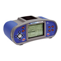
METREL EurotestXA MI 3105 Instruction Manual (136 pages)
multifunctional hand-held installation tester
Brand:
METREL
| Category:
Test Equipment
| Size: 2 MB
Table of Contents
Instruction Manual
1
Table of Contents
3
1 Preface
6
2 Safety and Operational Considerations
7
Warnings and Notes
7
Battery and Charging
10
New Battery Cells or Cells Unused for a Longer Period
11
Standards Applied
12
3 Instrument Description
13
Front Panel
13
Connector Panel
14
Back Panel
15
Bottom
16
Display Organization
17
Terminal Voltage Monitor
17
Menu Line
18
Message Field
18
Result Field
19
Other Messages
19
Sound Warnings
19
Help
19
Backlight and Contrast Adjustments
20
Carrying the Instrument
21
Instrument Set and Accessories
21
Standard Set
21
Optional Accessories
21
4 Instrument Operation
22
Main Menu
22
Single Test
22
Automatic Testing
24
Auto Sequence Number Main Menu
26
Auto Sequence Set
26
Test Parameters in Auto Sequence
27
Name and Description of Auto Sequence
27
Storing Auto Sequence Settings (Sequence, Number, Name)
29
Pause Flag and Comments in Auto Sequence
30
Setting Pause Flag and Comments
30
Building an Auto Sequence
32
Miscellaneous
36
Language
36
Supply System, Isc Factor, RCD Standard
37
Memory
39
Date and Time
39
Initial Settings
40
Communication Port
42
Locator
42
Operator
43
5 Measurements
44
Insulation Resistance
44
Resistance to Earth Connection and Equipotential Bonding
46
Continuity R200 Ma Measurement
46
Ma Resistance Measurement
48
Compensation of Test Leads Resistance
49
Testing Rcds
51
Contact Voltage (RCD Uc)
52
Trip-Out Time T
53
Trip-Out Current
54
RCD Autotest
55
Fault Loop Impedance and Prospective Fault Current
57
Line Impedance and Prospective Short-Circuit Current
59
Voltage, Frequency and Phase Sequence
61
Resistance to Earth
63
Standard 3-Wire Measurement
63
One Clamp Measurement
65
Two Clamps Measurement
66
Specific Earth Resistance Measurement
67
Current
68
Sensors and Adapters
70
Illumination
70
Ω Line/Loop Impedance
72
PE Test Terminal
74
Locator
76
Varistor Test
78
6 Data Handling
80
Memory Organization
80
Installation Data Structure
80
Storing Test Results
83
Saving Results Specialties
84
Recalling Test Results and Parameters
85
Recalling Result
85
Clearing Saved Data
86
Clearing Specialties
87
Editing Installation Data Structure
88
Adding New Locations
88
Communication
91
7 Maintenance
92
Replacing Fuses
92
Cleaning
92
Periodic Calibration
92
Service
92
8 Technical Specifications
93
Insulation Resistance
93
Continuity
94
Resistance R200Ma (L-PE, N-PE)
94
Resistance R7Ma (L-PE, N-PE)
94
RCD Testing
94
General Data
94
Contact Voltage RCD-Uc
95
Trip-Out Time
95
Trip-Out Current
96
Fault Loop Impedance and Prospective Fault Current
96
No Disconnecting Device or FUSE Selected
96
RCD Selected
97
Line Impedance and Prospective Short-Circuit Current
97
Voltage, Frequency, and Phase Rotation
98
Phase Rotation
98
Voltage
98
Frequency
98
Online Terminal Voltage Monitor
98
Earth Resistance
99
TRMS Clamp Current
101
Illumination
101
Ω Line/Loop Impedance
102
High Precision Line Impedance
102
High Precision Fault Loop Impedance
102
Contact Voltage
103
Varistor Test
103
General Data
104
A Appendix A - Fuse Table
105
B Appendix B - Accessories for Specific Measurements
108
C Appendix C - Locator Receiver R10K
109
Tracing Principles
110
Positioning the Receiver
110
Positioning Current Clamp
110
C.1 Tracing Principles
110
Positioning Selective Probe
111
Detection Distances for Different Connections
111
R10K Power Supply
111
Maintenance
111
D Appendix D - IT Supply Systems
112
Standard References
112
Fundamentals
112
Measurement Guides
113
D.3 Measurement Guides
113
Line Impedance
114
MI 3105 Test Functions and IT Systems
114
Voltage Measurements
114
D.3.4 RCD Testing
115
IMD Testing
115
RCD Testing
115
First Fault Leakage Current (ISFL)
117
Technical Specifications
119
First Fault Leakage Current ISFL
119
Calibrated Resistances for IMD Testing
119
D.4 Technical Specifications
119
E Appendix E - Reduced Low Voltage Supply Systems
120
Standard Reference
120
Fundamentals
120
MI 3105 Guides
120
MI 3105 Functions and Reduced Low Voltage Systems
121
Technical Specifications
123
Rcd
123
E.4 Technical Specifications
123
Fault Loop Impedance and Prospective Short-Circuit Current
125
Line Impedance and Prospective Short-Circuit Current
127
F Appendix F - Country Notes
128
List of Country Modifications
128
Modification Issues
128
AT Modification - G Type RCD
128
ES Modification - CONTINUITY LOOP Re
129
IT Modification - CONTINUITY LOOP Re
131
CH Modification - Change L/N
133
F.2.4 CH Modification - Change L/N
133
Advertisement
Advertisement
Related Products
METREL MI 3108 EurotestPV
Metrel MI 3108
METREL MI 3101
METREL MI 3100 SE EurotestEASI
METREL MI 3100 S EurotestEASI
METREL MI 3109
METREL EurotestEASI MI 3100
METREL MI 3100B SE
METREL EurotestXD MI 3155
METREL MI 3143
METREL Categories
Measuring Instruments
Test Equipment
Multimeter
Adapter
Motherboard
More METREL Manuals
Login
Sign In
OR
Sign in with Facebook
Sign in with Google
Upload manual
Upload from disk
Upload from URL