Sign In
Upload
Manuals
Brands
MERRICK Manuals
Controller
MC3
MERRICK MC3 Manuals
Manuals and User Guides for MERRICK MC3. We have
2
MERRICK MC3 manuals available for free PDF download: Operation And Maintenance Manual, Hardware Manual
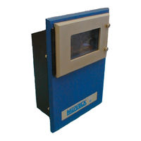
MERRICK MC3 Operation And Maintenance Manual (83 pages)
for the 24.96.EX.G Belt Feeder
Brand:
MERRICK
| Category:
Controller
| Size: 0 MB
Table of Contents
Table of Contents
3
Introduction
9
Safety
9
In General
9
Electrical Precautions
9
Manual Conventions
9
Buttons
9
Screens
10
Solving Problems
10
Help Button
10
Technical Support
10
System Concepts
11
Hardware
11
Enclosure
11
Backplane Board
12
Card Stack Assembly
12
CPU Board
12
PCAD Board
12
PCIO Board
12
LTI Board
12
Power Supply Assembly
12
Display Assembly
13
LCD Board
13
LCD Display
13
Touch Keypad
13
Software
13
Application Software
13
Bios
13
Register Database
13
Getting Started
14
Installation
14
Panel Mount
14
Wall Mount
14
Starting the Controller
14
Password Protection
15
Main Screens
15
Changing Main Screens
15
Feeder Screen
15
Graph Screen
16
Numerical Display
17
Entering New Values
17
Numeric Entry Screen
17
Sub Menus
18
Common Displays in Main Screens
18
Speed
18
Setpoint
18
Feedrate
18
Belt Load
18
Sub-Total
18
Total
18
Date and Time
18
Pulses
18
Blank Button
19
Setpoint
19
Logo
19
Start, Stop, Clear Batch
19
Indicators ( on Feeder Screen)
19
General Alarms
20
Belt Load over Limit
21
Belt Load under Limit
21
PCAD Near Zero
21
PCAD Near Full
21
Z Track out of Range
21
PCAD Discrepancy
21
Tachos Do Not Comply
21
Communications Lost
21
Setpoint out of Range
21
No Speed Detected
22
Anain out of Range
22
LCD Not Responding
22
No Data from PCAD
22
Controller Modes
22
Setpoint
23
Setpoint Screens
23
Batch Setpoint
23
Local
23
Remote Serial
23
Batch Parameters
23
Feedrate
24
Feedrate Setpoint
24
Manual Speed
24
Local
25
Remote Analog Input
25
Remote Analog Ratio
25
Remote Serial
25
Snap Button
25
Setpoint Button
25
Fallback Setpoint
26
Common Setpoint Buttons
26
Accept Button
26
Arrow Buttons
26
Return Button
26
Actions
26
Cal
26
Reset Total
26
Sub-Total
27
Clean Screen
27
Diagnostics
27
Alarms
27
Print
27
Print Line Editing and Printout Selection
27
PF Buttons
28
Setting up Your Controller
29
Setup
29
Chain Ez Setup
29
Weight Ez Setup
30
Custom Setup
31
Setup Screen 1
32
Units Select
32
List of Unit String Combinations
32
Decimal Points
33
Design Capacities
33
PID Parameters & Output Dynamic Protection
33
Gain
34
Integral
34
Derivative
34
SCR Accel %/S and SCR Decel %/S
34
Start Speed
34
Limit Switches
34
Feedrate HI/LO
35
Feedrate Rel Dev
35
Feedrate Setpoint Deviation
35
Numeric Parameters
35
Belt Parameters
36
Pulses / Rev
36
Length
36
Proc Revs
36
Speed Revs
36
Nominal Speed
36
Alarm Delay
36
Zero Tracking Parameters
36
Wait Time
37
Max Load
37
Max Step Alwd
37
Max Z Track
37
Tachometer Parameters
37
Type
37
Mode
38
Speed Sensing Operational Mode
38
Numeric Parameters
39
Setpoint
39
Totalizer Cut-Off
39
Calibration Parameters
39
Calibration Weight
39
E-Cal Liveload
39
Weigh Span
39
Chain Load
39
Calibration Speed
39
Display Dampening
40
Setup Screen 2
41
Analog Inputs
41
IN1 Zero Level / IN2 Zero Level
41
IN1 100% Level / IN2 100% Level
41
IN1 Scaling / IN2 Scaling
41
Analog Outputs
41
Mode
42
Type
42
Digital I/O Mapping
42
Mapping Inputs
43
Mapping Outputs
43
Inverting Inputs and Outputs
43
Forcing Inputs and Outputs
43
Available Logical I/O Points
44
External Physical I/O Points
44
Digital Inputs Setup
44
Tab
44
INV (Button) / RV (Indication)
45
FRC (Button) / FC (Indication)
45
List of Logical Inputs
45
List of Physical Inputs
46
Default Input Mapping
47
Digital Outputs
48
INV (Button) / RV (Indication)
48
FRC (Button) / FC (Indication)
48
Tab
48
List of Logical Outputs
49
List of Physical Outputs
50
List of Default Output Settings
51
Sample Rate
51
Internal Sample Rate Parameters
51
External Sample Rate Parameters
52
External Totalizer Parameters
52
Divide Value
52
Pulse Length
52
Communications
52
Baud Rate
52
Data Bits
53
Stop Bits
53
Parity
53
Numeric Parameters
53
Controller Number
53
Comp Start Code
53
Comp End Code
53
Communication Time-Out
53
Set Date and Time
54
PCAD Settings
54
Cal
54
Zero
54
Gain
54
Set Status
54
Number of Pcad's
54
Allowed Difference
54
Display Parameters
55
Calibrating Your Controller
56
Initial Calibration Checklist
56
Calibration Menu
56
Speed Calibration
57
Zeroing Procedure
58
Material Calibration
59
Scale Totalized
59
Actual Total
59
Chain Procedure
60
Chain Factor Procedure
61
Weight Procedure
61
Weight Factor Procedure
62
Electronic Calibration
62
E-Cal Factor Procedure
63
Grab Sample Calibration
64
Analog Input Setup and Calibration
64
Diagnosing Problems
66
Diagnostic Menus
66
PCAD Diagnostics
66
Out
66
PCAD1 and PCAD2
66
Abs
66
Cnts
67
Z Ld
67
Settings
67
Scale Factor
67
Communication Diagnostics
67
Rx Buffer
67
Tx Buffer
67
Error Counters
67
Iir
68
Lsr
68
Communication Parameters
69
Tacho Diagnostics
69
Emt Puls
69
Tst
69
Blt Trvl
69
Curr Ratio
69
Diff
69
Analog I/O Diagnostics
70
Digital I/O Diagnostics
70
Register Monitor
70
Register Editor
71
Advanced Setup
71
Quick Setup
71
Solving Problems
72
Unit Does Not Power up
72
Controller Fails to Boot up
72
LCD Display too Dark or too Light
73
No Load, or Bad Load Reading
73
Tacho Not Counting Pulses, or no Speed Indication
73
No Analog Input
73
External Totalizer Problems
73
General Alarms
73
No Serial Communications
74
Hang Message Appears
74
Hardware Calibration and Testing
74
Analog Outputs
74
Analog Inputs
74
Pcad
75
Simulator
75
Working with Inputs and Outputs
76
Lti Board
76
Emt
76
Tacho
76
Serial Communications
76
Pcio Board
77
Digital I/O
77
Digital Inputs
77
Digital Outputs
77
Analog I/O
77
Analog Inputs
77
Analog Outputs
78
Pcad Board
78
Keyboard Location Codes
78
Printer Port
78
Storage
79
Storage on Receipt from Factory
79
Storage Longer than 6 Months
79
Storage up to 6 Months
79
Storage Following Use
79
Operation after Storage
79
Spare Part List
80
MC³ Controller Spare Parts List
80
Accessories for the MC³ Controller
80
I/O System
80
Spare I/O Plugs
80
Miscellaneous
80
Feeder Connection
81
Appendix A
82
MC³ Panel Mount - Dimensions
82
Wall Mount - Dimensions
83
Advertisement
MERRICK MC3 Hardware Manual (58 pages)
Brand:
MERRICK
| Category:
Controller
| Size: 3 MB
Table of Contents
Table of Contents
3
Introduction
6
Controller Enclosures
7
Panel Mount
7
Wall Mount
7
Door Mount
8
Installation
9
Physical Installation
9
Panel Mount
9
Wall Mount
9
Door Mount
9
Card Stack Assembly
10
Connections
10
Card Stack with Revision 11 or Newer CPU Board
11
Card Stack with Revision 10 or Older CPU Board
12
Controller Disassembly
13
Controller Reassembly
13
CPU Board
14
New CPU Board (Rev 11 or Newer)
14
Communication Ports
14
Com 1 Rs-232 J7
14
Com 1 Rs-485 4 Wire J6
14
Com 2 Rs-232 J4
15
Com 2 Rs-485 4 Wire J5
15
Board Features
15
Option Switch Settings
16
LED Display
16
Jtag/Service Port (J8)
16
Old CPU Board (REV 10 or Older)
17
Communication Ports
17
Comm 2 (RS-232)
17
Board Features
18
Jumper Settings
18
Printer Operation (Old CPU Only)
18
HPAD Board
20
Straps
20
HPAD 1/2 Determination
20
PCIO Board
22
PCIO 1/2 Determination
22
Connections
23
Analog I/O Current/Voltage Strapping
23
Analog Input
23
AIN Adjustments
24
Analog Outputs
24
AOUT Adjustments
24
Adding an Additional PCIO Board to a MC Controller
24
LTI Board
25
Connections
25
Serial Communications (for Older CPU Boards)
25
Encoder
26
Emt
26
Backplane Boards
27
DC Style Backplane Board - BKPN
28
AC Style Backplane Board - BPAC
29
Power Supply Assemblies
30
MC 3 DC Power Cables
30
MC 3 DC Power Cable Details
32
Power Receptacle and Switch
32
Display Assembly
34
LCD Board
34
Brightness and Contrast Adjustments
34
LCD Display
35
Replacing Backlight Assembly
35
Touch Keypad
35
Touch Screen Location Codes
36
MC 3 Troubleshooting
37
1100 MC Troubleshooting
37
MC³ Crash Screens
37
Start-Up Crash
37
Parameter Corruption
37
Controller Firmware Upgrade
37
Fatal Error Crash
38
Forcing a Parameter Reset
39
Controller Reboots and Displays Ram Reset Screen
39
Unit Does Not Power up
39
LCD too Dark/Light or out
40
No Belt Load or Weight
40
No Speed Detected
41
Analog Output Problem
41
Analog Inputs
41
MC3 Flashloader Programming (Application Upgrade)
43
Procedure for Rev 10 or Earlier CPU Boards
44
Procedure for Rev 11 or Later CPU Boards
45
Sample Session
46
Storage
47
Storage on Receipt from Factory
47
Storage Longer than 6 Months
47
Storage up to 6 Months
47
Storage Following Use
47
Operation after Storage
47
Spare Part List
48
MC³ Controller Spare Parts List
48
MC³ Panel Mount A30685
48
MC³ Wall Mount A30833, A31534, A37244
48
MC³ Door Mount A33432 (Hitachi)
49
MC³ Door Mount A39307 (Hantronix)
49
Accessories
49
I/O System
49
Options (Communication)
50
Spare I/O Plugs and Miscellaneous
50
Feeder Connection Board (FCB)
50
Appendix A
51
Appendix A
51
Panel Mount (A30685) - Dimensions
51
Wall Mount (A30833, A31534) - Mounting Dimensions
53
Wall Mount - Mounting Dimensions Cont
54
Door Mount (A33432, A39307) - Dimensions
55
Door Mount Power Supply (VL30) Mounting Dimensions (A36539)
56
Door Mount Power Supply Mounting Dimensions (S60213, 19-102-32402)
56
Backplane Mounting Dimensions (M21882, M22108, M22535)
57
Watchdog Timer Board Mounting Dimensions (N41215)
57
IOC Input Connection Board (M22536)
58
Advertisement
Related Products
MERRICK MC3 35.00.EX
MERRICK MC3 90.10.EX
MERRICK Genetix
MERRICK Genetix GCM
MERRICK Categories
Controller
Recording Equipment
Wire Feeders
More MERRICK Manuals
Login
Sign In
OR
Sign in with Facebook
Sign in with Google
Upload manual
Upload from disk
Upload from URL