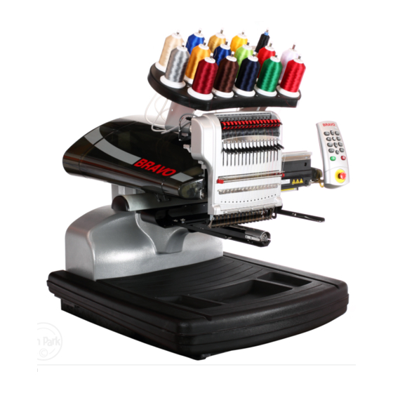
Sign In
Upload
Manuals
Brands
Melco Manuals
Sewing Machine
Bravo
Melco Bravo Manuals
Manuals and User Guides for Melco Bravo. We have
1
Melco Bravo manual available for free PDF download: Technical Manual
Melco Bravo Technical Manual (272 pages)
Brand:
Melco
| Category:
Sewing Machine
| Size: 7.13 MB
Table of Contents
Contents
2
Liquid Cleaning Compounds
15
Obstructions
15
Use Proper Parts for the Job
15
Use the Correct Tools When Making Repairs
15
Drive Belt Tensions
16
Scheduled Maintenance
16
Lubrication
16
Torque Measurements
16
Static Electricity
17
Grounding Strap Use
17
Machine Orientation
19
Voltages
20
Explanation of Machine Symbols
22
Keypad Operations
23
Keypad Buttons
26
Trace Button
26
Arrow up Key (Y-Axis Back)
26
Color Change/Needle Case
26
Arrow Right Key (X-Axis Left)
27
Center Key
27
Adjustment Key
27
Arrow down Key (Y-Axis Forward)
27
Hoop Key
28
Step Back Key
28
Step Forward Key
28
Laser Key
28
Stop Button
29
Emergency Stop Button
29
LED Indicator
30
Specifications
31
Technical Specifications
33
Torque Specifications
34
Software Maintenance Menus
36
Special Tools and Fixtures
37
General Maintenance
38
Cleaning
38
Exterior Surfaces
38
Interior Surfaces (PCB)
38
Rotary Hook and Trimmer Assembly Area
39
Lubrication Schedule and Specifications
40
Maintenance Schedule
40
Daily Maintenance
40
Weekly
40
Monthly
41
Quarterly
41
Yearly
41
Weekly Maintenance
43
Needle Drive
43
Left Upper V-Rail
44
Right Upper V-Rail
44
Oil Needle Bars (Lower)
44
Monthly Maintenance
45
Oil Needle Bars (Upper)
45
X-Drive Rails
45
Y-Bearing Blocks
47
X-Cable Tension (Test)
48
Quarterly Maintenance
51
Thread Cutter Blade Replacement
61
Centering the Needle Plate
62
Head up Position Adjustment
63
Mechanical Head-Up Position
63
Adjusting Head-Up (Z-Home) Position
64
Hook Timing Inspection/Adjustment
65
Rotational Hook Timing Inspection Procedure
65
Needle to Hook Gap Inspection Procedure
67
Adjustment Procedure
67
Thread Clamp Replacement
71
Thread Clamp PCB Replacement
72
Thread Clamp Harness Replacement
72
Laser Light - Adjustment
74
Laser Light Focus
75
Laser Lens
75
Needle Depth
76
Setting the Needle Depth by Eye
76
Presser Foot Height
77
X/Y Home Adjustment
78
Home Adjustment Procedures
78
Determining if an X-Cable Is Set to Required Specifications
81
Adjusting X-Cable that Is Tensioned Outside Required Specifications
82
Centering the X-Carriage
82
Positioning the X-Cable Tension Gauge
82
Inspecting X-Cable Tension
82
Adjusting the Tension on a Replacement X-Cable
83
X-Cable Tension Adjustment
83
Y-Axis Timing Belt Tensioning
84
Y-Axis Belt Tension Inspection
84
Y-Axis Belt Tension Adjustment
85
When Belt Tensions Are Correct
85
Y-Motor Timing Belt Tensioning
86
Inspection and Adjustment
86
Z-TIMING: Bottom Center & Head-Up
87
Bottom Center (Z Timing)
87
Needle Clamp and Weight
88
Turn Z-Axis Flag Counter-Clockwise (CCW)
88
Dial Indicator Installed on Needle Plate Bracket
89
Z-Index LED (Location D50)
90
Z-Drive Belt Tensioning
92
Procedure to Identify the Closest Needle
95
Needle Case Calibration
98
Fine Calibration Procedure
98
Rough Calibration Process
99
Get Table Button
100
Rotary Hook Support Adjustment
101
Hook Retaining Finger Gauge
101
Needle Plate Screws
101
Head Timing Tab
102
Hook Support Position Left-To-Right
102
Retaining Finger Gauge Usage
103
Hook Support Screws
103
Rotary Hook Basket Notch
103
Hook Support Adjustment
104
Color Change, Take-Up, Feeder Housing Assembly
105
Replacement Procedure for Entire Color Change/Take-Up/Feeder Assembly
105
Color Change Linear Actuator Replacement
107
Color Change Linear Actuator
107
Right Color Change Spindle Mounting Bracket
107
Anti-Backlash Nut
108
Left Color Change Spindle Mounting Bracket
108
Thread Feeder Gear Replacement
110
Thread Feeder Optical Sensor PCB Replacement
112
Thread Feeder Assembly
112
Thread Feeder Radial Bearing Replacement
113
Radial Bearing
113
Radial Bearing Behind Needlecase
113
Thread Feeder Stepper Motor Assembly
114
Thread Feeder Stepper Motor
114
Steppers Menu
115
Laser Pointer Assembly
116
LED Cluster PCB Replacement
118
LED Cluster Assembly
118
Presser Foot Assembly Replacement
119
Presser Foot Assembly Installed
119
Wire Installed through Take up Levers
119
Reciprocator
122
Reciprocator Assembly Installed
122
Reciprocator Assembly
122
Take-Up Lever Cam Replacement
124
Take-Up Lever Connecting Arm
124
Remove Center Screw
124
Screws on Back of Take-Up Lever Cam
125
Remove Hex Nut
125
Endplate W/Spring Pin Pressed in Endplate- Back View
125
Alignment Groove in Z-Shaft
125
Z-Drive Repair and Adjustment
127
Z-Drive Belt Replacement and Tensioning
127
Z-Motor Drive Belt
127
Z-Home Flag with Index Mark
128
Lower Z-Shaft Drive Pulley
128
Z-Home Sensor PCB Replacement
129
Z-Home Sensor Fixture
129
Z-Home PCB Mounting Bracket
130
Cable Tie Around PCB
130
Z-Belt Idler Assembly Replacement
131
Z-Belt Idler Pulley
131
Index Mark on Z-Index Flag
131
Lower Z-Shaft Pulley
131
Z-Motor Assembly
132
Measuring Resistance between Motor Phase Wires
132
Z-Motor PCB Connections
132
Z-Motor Mounting Screws
133
Clearing Thread from Thread Feeder Roller
135
Removing Thread Feeder Front Cover
135
Prying Thread Feeder Roller Loose
135
Pulling Thread Feeder Roller out
135
Color Change Spindle Mounting Bracket Replacement
137
Grabber Blade Replacement
139
Grabber Blade (Bottom View)
139
Upper Trap Assembly Front Screw
139
Upper Trap Assembly Hex Nut
140
“Steppers” Submenu
141
Needle Case Removal
142
Needlecase Assembly
142
Needlecase Access Cover Removed
143
Loosen Top Screw
143
Remove Nut
143
Remove Thread Tubes
143
Needlecase Installation
144
Reciprocator at “Head Up” Position
144
Grabber Stepper Motor Replacement
146
Grabber Eccentric
146
Grabber Stepper Motor Mounting Screws
146
Take up Lever Replacement
147
Right Take up Lever Bar Mounting Block
147
Screws on Take up Lever Bar
147
Retaining Clip
148
Thread Feeder (Replacement and Adjustment)
149
Needle Case Assembly
149
Thread Tubes Connected to Thread Feeder Assembly
149
Thread Feeder Assembly, Left Bracket
149
Thread Feeder Assembly, Right Thread
150
Thread Feeder Gears
150
Gage Pin
151
Thread Feeder Clicker
151
Thread Sensor Assembly Replacement
152
Bobbin Shaft Overhaul
154
Bobbin Shaft Front View
154
Bobbin Shaft Timing Pulley (Rear)
154
Rotary Hook Replacement
156
Main PCB
158
Main PCB Installed
158
EMI Cover
159
Power Input Assembly Replacement
160
Power Input Assembly Removal
160
Power Supply Ground Wires
160
Power Input Assembly Component Replacement
161
Power Supply Harness Connection
161
In-Line Coupler
161
Power Input Switch Replacement
162
Bottom Wiring Block (Switch Interface Leads)
162
Top Wiring Block (Wire Leads from Power Interface Harness)
162
Fuse Replacement
163
Power Input Switch (with Fuse)
163
Power Input Switch Wiring
163
Fuse Holder
163
Power Switch Interface Harness Replacement
164
Power Switch Interface Harness Wiring to Power Supply
164
Power Switch Interface Harness Wiring to Switch
164
Power Supply Interface Harness Replacement
165
Power Supply Interface Connector
165
Power Supply Interface Harness Wiring to Power Supply
165
Power Input Assembly Installation
166
User Interface Assembly Replacement
167
User Interface
167
Keypad Submenu
167
Keyboard Harness Connection
168
Harnesses
170
Color Change Motor Harness
171
Color Change Harness Connection to Motor
171
Right Wire Channel
172
Harnessing Routed under Y-Motor
172
Wire Access Hole
172
Ethernet Harness
174
Ethernet Harness Connected to Coupler
174
EMI Cover over Main Board
175
Ethernet Connector Location on Main PCB (J1)
175
Grabber/Threadfeed Motor Harness
176
Grabber Motor Lead
176
Thread Feed Motor Lead
176
Grabber/Thread Feed Motor Connection at PCB
177
Harness Tie at Top Left of Needlecase Assembly
178
Grabber/Threadfeed/CC Home Harness
179
Grabber Home Harness Lead
179
Thread Feeder Home PCB
180
Grabber/Threadfeed/CC Harness Connection at Main PCB
180
Laser Harness
182
Laser Harness Connection to Laser Pointer Assembly
182
Right Upper Arm Access Hole
183
LED Cluster Harness
184
Left LED Cluster Harness
184
LED Cluster Harness Tied to Z-Motor Mounting Bracket
184
Left Lower Arm Access Hole
185
LED Cluster Harnesses Connected at Main PCB
185
Right LED Cluster Assembly
186
Right LED Cluster Harness
186
Thread Break Harness
188
Threadbreak Harness Connected to Sensor PCB
188
Connection at Main PCB
189
Routing of Harness to Top of Needlecase
189
Z Home Harness
191
Connection to Z-Index PCB
191
Connection to Main PCB (J32)
192
User Interface Harness
193
User Interface Harness Connection
193
User Interface Harness in PCB
194
X/Y Home Harness
195
Connection at X/Y Home PCB
195
Retaining Clip in Channel of Y-Home Flag
195
X/Y Home Harness Access Hole
195
X/Y Harness Connected at Main PCB (J3)
196
Bearing Block Assemblies
197
Y-Rail Retaining Screw
198
X-Beam Assembly
199
X-Beam and Carriage Installed on Machine
199
Cable Bracket Removal
199
Bearing Block Assembly Installed on Machine
199
X-Carriage Assembly
201
Remove Two Screws on Cable Pulley Bracket
201
X-Drive Cable Removal
203
X-Cable Removal Procedure
203
Cable Tensioner Bracket
204
X-Drive Cable Installation
205
X-Cable Assembly Installation
205
X-Cable Spool (Taped and Installed)
206
Right Rear Pulley
206
Right Rear Pulley Close up
206
Right Beam Cable Pulleys
207
Center Beam Cable Pulley
207
S 7 - X-Cable Clamp
207
Left Rear Cable Pulley
207
Left Beam Cable Pulleys
208
Cable Tensioning Bracket (Left Side of Machine)
208
X-Drive Motor Replacement
209
Wrap Tape Around X-Drive Pulley
210
X-Cable Tensioning Screw
210
X-Motor Harness Connections
211
X-Motor Mounting Screws
211
X-Home Optical Switch Assembly Replacement
212
X-Home Sensor Mounting Bracket
212
X-Home Sensor and Mounting Screws
212
X/Y Home PCB Replacement
214
Y-Drive Belt Replacement
216
Y-Drive Belt Adjusting Nuts (Left Side)
216
Left Timing Belt Clamp and X/Y Home PCB
217
Right Y-Drive Timing Belt Clamp
217
Y-Motor Assembly
218
Y-Motor Installed
218
Y-Motor Connections at PCB
219
Grabber Function Test
221
Final Functional Tests
223
Visual Inspection
223
Functional Tests
223
Burn-In
223
Test Sew Outs
224
Optical Sensors Test
225
Power Supply Test
226
Check the Power Supply Unit Itself
226
Power Supply Voltage Measurement Points
226
Power Supply Unit Terminal Jumpers
227
Power Supply Indicator LED
227
Servo Motor Resistance Test
229
Stepper Motor Resistance Test
230
Resistance Measurement of Servo Motors
231
Troubleshooting Stepper Motors
232
Grabber Phase Indicator Leds
233
Test Designs
235
Thread Tension Test
236
Belt Tension Test
237
Long Stitch Test
237
Looping Test
237
Orientation Test
238
Registration Test
238
Small Alphabet Test
238
Thread Break Sensor Test
239
Thread Break Test
239
Trimmer Test
240
Electrical Failures
241
AC Power Failure
241
Color Change Failures
241
LED Cluster Assembly Failures
242
Machine Initialization Failure
242
Mechanical Failures
244
False Thread Breaks
244
Loose/Looping Stitches
244
Needle Breaks
244
Skipped Stitches
245
Thread Breaks
246
Miscellaneous Problems
251
X-Axis Failures
252
Z-Axis Failures
254
Software Error Messages
255
DSP Command Errors
256
Can’t Initialize Stepper Motors
256
No Trace Data
256
XY Home Not Set
256
Goto Func Error
257
Hoop Center Error
257
Stepper Motor Time out and Index Errors
257
E-Stop Engaged
258
Possible Causes of a False E-Stop Engaged Message
258
Servo Motor Errors (Move Time Out, Tracking, and over Current Errors)
260
Critical Measurements
262
Contents & Critical Mechanical Settings and Assemblies
262
Needle Drive Stud to Reciprocator Fit
263
Hook Timing
263
Upper Arm to Lower Bed Alignment
263
Needle to Hook Gap
264
Hook to Rotary Support Gap
264
Take-Up Lever Stroke
264
Head Alignment Procedure
264
Take-Up Lever Fit to Shaft
265
Take-Up Lever Endplay
265
Cam Follower Preload
265
Pull Force on Take-Up Lever
266
Color Change Lead Screw
266
Color Change Housing Location
267
Bobbin Tension
267
Presser Foot Adjustment at Bottom Dead Center
268
Checking Bobbin Tension
268
Thread Feed Forward 200
269
Thread Feed Forward Measurement
269
Needle Orientation
269
Thread Clean Thread Path
270
Z-Belt Tension
270
X-Cable Tension
271
Y-Axis Timing Belt Tension
271
Proper Lubrication of Moving Parts
271
Advertisement
Advertisement
Related Products
Melco Buffalo RoamLAN WLI-PCM
Melco EM-I
Melco EMC-6
Melco EMT 1
Melco EMT 10/4
Melco EMT 10/4T
Melco EMT 10T
Melco EMT16X
Melco EP 1
melco EP 1B
Melco Categories
Sewing Machine
Media Converter
PDA
Server
Switch
More Melco Manuals
Login
Sign In
OR
Sign in with Facebook
Sign in with Google
Upload manual
Upload from disk
Upload from URL