Sign In
Upload
Manuals
Brands
Meister Manuals
Control Unit
DWG-8
Meister DWG-8 Manuals
Manuals and User Guides for Meister DWG-8. We have
1
Meister DWG-8 manual available for free PDF download: Operating Instructions Manual
Meister DWG-8 Operating Instructions Manual (89 pages)
Flow Monitor
Brand:
Meister
| Category:
Control Unit
| Size: 1 MB
Table of Contents
Table of Contents
4
1 Overview
10
Short Description
10
Warranty and Guarantee Provisions
10
Customer Service
10
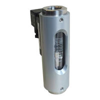
Fig. 1: DWG Flow Monitor
10
2 Safety
11
Explanation of Symbols
11
Correct Use in Accordance with These Instructions
13
Special Precautions
14
Hazards from Electrical Current
15
Mechanical Hazards
15
Hazards from High or Low Temperatures
16
Radiation Hazards
17
Hazards Caused by Media
17
Personnel Requirements
18
Personal Safety Equipment
18
Protective Systems
19
Replacement Parts
20
Environmental Protection
20
Responsibility of the Owner
21
3 Design and Function
23
Overview
23
Device Description
23
Fig. 2: Front View
23
Component Description
24
Fig. 3: Switch Contact and Female Socket
24
Fig. 4: Sight Glass
24
4 Transport, Packaging and Storage
25
Safety Instructions for Transport
25
Transport Inspection
25
Packaging
25
Symbols on the Shipping Box
26
Storage
26
5 Installation und Initial Startup
28
Safety
28
Requirements at the Place of Installation
28
Preparatory Work
29
Fig. 5: Installation Position/Direction of Flow
29
Fig. 6: Unimpeded Flow Section
31
Fig. 7: Unimpeded Outlet
31
Fig. 8: Strainer
32
Installation in the Pipe System
33
Fig. 9: Apply Sealing Thread
35
Fig. 10: Pipe Connection with Sealing Thread
35
Fig. 11: Screw in the Device
36
Fig. 12: Screw in the Device
36
Initial Startup
37
Electrical Connection
38
En175301-803
39
Fig. 13: Switch Position under No-Flow Condition
39
Fig. 14: Pin Assignment, Plug Socket, Normally-Open Contact. the Ground-Pin Is Not Used
39
Fig. 15: Switch Position under No-Flow Condition
39
Fig. 16: Pin Assignment, Plug Socket, Change-Over Contact. the Ground-Pin Is Not Used
39
Switch Contact SG-30 with Plug Connector M12X1
40
Fig. 17: Pin-Assignment, Socket M12X1 (Form 30X70)
40
Fig. 18: Switch Position under No-Flow Condition
40
Fig. 19: Switch Position under No-Flow Condition
40
Switch Contact SG-30 with Cable
41
Fig. 20: Switch Position under No-Flow Condition
41
Degree of Protection (IP-Code)
42
Grounding the Device
42
Fig. 21: Switch Position under No-Flow Condition
42
Plug Connection
43
Fig. 22: Detach Socket
43
Fig. 23: Remove Socket
43
Fig. 24: Loosen Inner Section
43
Fig. 25: Loosen the Screw Connection
44
Fig. 26: Pin Assignment, Plug
44
Contact Protection Measures
45
Fig. 28: Example 1
45
Fig. 29: Example 2
45
Fig. 30: Protective Measure against Capacitive Loads
46
Fig. 31: Example 1
46
Fig. 32: Example 2
46
6 Operation
47
Setting the Switch Point
47
Fig. 33: Loosen Set Screws
47
Fig. 34: Loosen Set Screws
48
Checking the Flow
49
Fig. 35: Reading-Off the Measuring Scale
49
7 Troubleshooting
51
Safety
51
Troubleshooting Guide
53
8 Maintenance
55
Safety
55
Maintenance Plan
55
Removal from the Pipe System
56
Disassembly
58
Fig. 36: Loosen Screws
59
Fig. 37: Remove the Process con
59
Fig. 38: Slot Nozzle Buffer O
60
Fig. 39: Loosen Screws
60
Ring
60
Maintenance
61
Fig. 40: Remove the Inner Sec
61
Fig. 41: Remove Slot Nozzle
61
Cleaning
62
Parts Replacement
63
Assembly
63
Fig. 42: O-Ring (Seal)
63
Fig. 43: O-Ring (Glass Buffer)
64
Fig. 44: Position of O-Rings
64
Fig. 45: O-Ring (Centering the Slot Nozzle)
64
Fig. 46: Insert Slot Nozzle
65
Fig. 47: Centering the Slot
65
Fig. 48: Float
66
Fig. 49: Process Connection (Inlet)
66
Fig. 50: Spanner Flats
67
Fig. 51: Insert the Process con
67
Fig. 52: Secure the Process Con- Nection (Inlet)
67
Fig. 53: Align Slot Nozzle
68
Fig. 54: O-Ring, Slot Nozzle
68
Fig. 55: Position the Outlet Process Connection
69
Fig. 56: Tighten Hex Socket
69
Switch Contact Replacement
70
Fig. 57: Check for Free Move
70
Fig. 58: Loosen Female Socket
70
Fig. 59: Remove the Female
70
Fig. 60: Loosen Set Screws
71
Fig. 61: Release the Guide Rail
71
Fig. 62: Rotate Guide Rail to the
71
Fig. 63: Remove Switch Contact
71
Measures to be Taken after Maintenance Work
72
9 Disassembly and Disposal
73
Safety
73
Disassembly
73
Return Materials
74
Return Materials Authorization
74
Disposal
74
10 Technical Data
75
Device Data Plate
75
Switch Contact Data Plate
75
Switch Contact Data Plate for UL Recognized Switch Contacts
75
Fig. 64: Device Data Plate
75
Fig. 65: Switch Contact Rating
75
Fig. 66: Switch Contact Rating
75
Fig. 67: Switch Contact Data
75
Fig. 68: Adhesive Label, Switch
75
Dimension Sheet
76
General Specifications
77
Electrical Specifications
79
Electrical Specifications for UL Recognized Devices
80
Measuring Ranges
81
Standard Measuring Ranges
81
Operating Data
82
11 Annex
84
Tightening Torque of Screws
84
Replacement Parts
84
Fig. 69: Replacement Parts Drawing
85
Tools
86
Sealant
86
Lubricants
87
12 Index
88
Advertisement
Advertisement
Related Products
Meister DWG Series
Meister DWG-1
Meister DWG-18
Meister DWG-3
Meister DWG-35
Meister DWG-50
Meister DWG-12
Meister DWM/A-L
Meister Categories
Power Tool
Power Screwdriver
Drill
Saw
Sander
More Meister Manuals
Login
Sign In
OR
Sign in with Facebook
Sign in with Google
Upload manual
Upload from disk
Upload from URL