Sign In
Upload
Manuals
Brands
Meech Manuals
Fan
VacClean
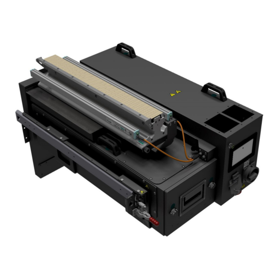
User Manuals: Meech VacClean Contact Web Cleaning
Manuals and User Guides for Meech VacClean Contact Web Cleaning. We have
1
Meech VacClean Contact Web Cleaning manual available for free PDF download: Operating Manual
Meech VacClean Operating Manual (102 pages)
Brand:
Meech
| Category:
Fan
| Size: 17 MB
Table of Contents
Table of Contents
2
Table of Figures
5
Safety Instructions
8
General Safety
8
Electrical Safety
8
Warning and Information Labels
9
Danger Mains Voltage
9
Caution Hot
9
Do Not Cover
9
Figure 1 - Danger Mains Voltage, Warning Label
9
Figure 2 - Caution Hot, Warning Label
9
Figure 3 - Do Not Cover, Warning Label
9
Crushing of Hands
10
Vacuum Airflow
10
Operator Identification Sticker
10
Figure 4 - Pinch Point, Warning Label
10
Figure 5 - Vacuum Airflow, Information Label
10
Figure 6 - Operator Identification Sticker
10
External Earth Connection Label
11
AHU-CL1 Product Label
11
Vacclean Product Label
11
Figure 7 - Earth Connection Sticker
11
Figure 8 - AHU-CL1 Product Label
11
Figure 9 - Vacclean Product Label
11
924IPS Product Label
12
Meech Serial Number / Bar Code
12
Figure 10 - 924IPS Product Label
12
Figure 11 - Meech Serial Number / Bar Code
12
Figure 12 - Vacclean Head
13
Figure 13 - AHU-CL1
13
Figure 14 - 924IPS Bars
13
Figure 15 - Rear Manifold
13
What Is Included
13
Figure 16 - Side Slides
14
Figure 17 - Y-Splitter Connection Cable
14
Figure 18 - Toggle Latches
14
Figure 19 - Mounting Carriers
14
Figure 20 - Mounting Spacer
14
Unpacking the AHU-CL1 and Vacclean
15
Pallet Based Cardboard Container
15
Figure 21 - Palletised Cardboard Container
15
Figure 22 - Removing Lid of Palletised Container
15
Figure 23 - Removing Sides of Palletised Container
16
Figure 24 - Remaining Boxes on Palletised Container
16
Wooden Packing Crate
17
Figure 25 - Complete Crate
17
Figure 26 - Clip and Lid Removal
17
Figure 27 - Wooden Crate Lid Removed
18
System Overview
19
Ahu-Cl1
19
Figure 28 - System Overview
19
Figure 29 - AHU-CL1, Main Components
20
Vacclean Manifold
21
Function
21
Figure 30 - Vacclean Head, Main Components
21
924IPS Ionising Bars
22
Function
22
Figure 31 - 924IPS Ionising Bars
22
Rear Duct Manifold
23
Function
23
Figure 32 - Read Duct Manifold
23
Side Slides, Mounting Carriers and Toggle Latches
24
Function
24
Figure 33 - Side Slides, Mounting Carriers and Toggle Latch
24
System Installation Mechanical
25
Installation Procedure
25
Installing the Rear Manifold
25
Figure 34 - Rear Manifold Mounting Flanges
25
Figure 35 - Mounting Top Flange Screws in Rear Manifold
26
Figure 36 - Mounting the Rear Manifold Side Flanges
26
Install the Side Slide Rails
27
Figure 37 - Pair of Side Slide Rails
27
Figure 38 - Side Slide Mounting Holes
27
Figure 39 - Side Slide in Position
27
Figure 40 - Fixing Side Slide
28
Figure 41 - Rear Manifold and Side Slides in Place
28
Install the Top Vacclean Manifold
29
Figure 42 - Top Vacclean Manifold
29
Figure 43 - Angled Top Manifold for Fitting
29
Figure 44- Getting Top Manifold in Rough Position
30
Figure 45 - Screwing Front Bracket in Place with Spacer
30
Figure 46 - Vacclean 0.5Mm Brush Gap
31
Figure 47 - Join between Rear Manifold and Vacclean Ducting
31
Fitting the Mounting Carriers
32
Figure 48 - Mounting Carriers
32
Figure 49 - Side Slides Fully Extended
32
Figure 50 - Fitting the Mounting Carriers
33
Figure 51 - Mounting Carriers Level
34
Figure 52 - Slide the Mounting Carriers Back into Machine
34
Install the Toggle Latches
35
Figure 53- Left and Right Toggle Latch
35
Figure 54 - Fitting of Left and Right Toggle Latch
35
Mount the AHU-CL1
36
Figure 55 - AHU-CL1 6 Mounting Stud Locations
36
Figure 56 - Disengaging Toggle Clamps and Pulling out the Mounting Carriers
36
Figure 57 - Lowering AHU-CL1 into Place
37
Figure 58 - Position of M5 Bolts to Secure AHU-CL1
38
Figure 59 - Moving Rear Mounting Handle
38
Figure 60 - AHU-CL1 in Position with Handle Moved
39
Figure 61 - Caution with Top Inductive Sensor
39
Figure 62 - AHU-CL1 Awaiting Toggle Latches
40
Figure 63 - Locking Toggle Latches in Place
40
Connect the 924 Bars
41
Figure 64 - Cable End Bar Connection
41
Figure 65 - 'Y' Splitter Cable Connection
41
Suggested Order of Installation
25
Figure 66- Electrical Connection on AHU-CL1
42
3-Phase Supply
43
Figure 67 - 3 Phase Connection
43
Signal Connection
44
Figure 68 - Signal Cable Connection
44
Filter Blocked Signal
44
System Running Signal
44
Figure 69 - Signal Connection Pin Layout
45
Figure 70 - Signal Connection Pin Colours
45
Figure 71 - M12 Female 8 Pole Connector
45
Remote Start/Stop Switch
45
Signal Connector Pin Schematic
45
Figure 72 - Inductive Sensor Location
46
Figure 73 - Filter Bag Inductive Sensor Location
46
Connecting the 924 Bars
47
Figure 74 - AHU-CL1 Position Inductive Sensor
47
How to Test the Inductive Sensors Are Functional
47
Inductive Sensor Connection
46
System Installation Electrical
42
Quick Start Guide
48
How the AHU-CL1 Works
49
Figure 75 - AHU-CL1, Main Components
49
Touch Screen Control Interface
50
Behaviour of AHU-CL1
52
Local Mode Behaviour
52
Remote Mode Behaviour
52
Remote Star/Stop Control
52
Filter Blocked Signal
52
AHU-CL1 Running Signal
52
Behaviour Flow Diagram for Remote Running
53
Figure 77 - Remote Running Behaviour Flow Diagram
53
Filtration
54
Emptying/Replacing the Filter Bag
54
Figure 78 - Rotating Filter Locks
54
Figure 79 - Filter Draw Open
54
Filter Disposal
55
Figure 80 - Removal of Filter Housing
55
1 Vacuum/Pressure Level Indicator
50
Figure 76 - Main Home Page on Touch Screen
50
2 Vacuum/Pressure Target Set Pressure Value and Setting Buttons
50
3 System Status Indicator
50
4 Filter Status Indicator
51
5 Local/Remote Toggle Buttons
51
6 Start/Stop Button
51
7 Support Button
51
Figure 81 - Vacclean Parts with Detailed View
56
How It Works
57
Maintaining Pressure
57
Figure 82 - Web Passing through Vacclean Head
57
Figure 83 - Vacuum Pressure on
57
Figure 84 - Vacuum Pressure off
57
Figure 85 - How the Plastic Fingers Are Pulled down to Faceplate
58
Figure 86 - Plastic Fingers Covering Faceplates
58
Figure 87 - 0.5Mm Brush to Faceplate Gap
58
Turbulent Air
59
Installation
59
Vacclean Specific Installation
59
Inspecting Face Plate Level
59
Figure 88 - Removal of Contamination through Turbulent Air
59
Checking Brush Height
60
Multi-Web Size Fingers
60
Location of Ionising Bars
60
Vacclean
56
924IPS Bars
61
Operation
61
Bar Master
61
Figure 89 - Barmaster
61
Clean Pin Alert LED
62
Recommended (Pre-Set) Settings
62
Health and Safety
62
Emission of Ozone
62
Shockless Emitters
62
924 Bar Technical Drawing
63
Commissioning / Testing Effectiveness
64
Commissioning Test Procedure
64
Spares and Wear Parts
66
Spares and Wear Parts (Continued)
67
Spare Part Location Drawing
68
How to Replace Wear Parts
70
Plastic Finger Covers
70
Figure 90- Removal of Plastic Fingers
70
Figure 91- Plastic Fingers Removed
71
Figure 92 - Removal of Finger Retaining Strip
71
Figure 93 - Locating Detail for Finger Holder
72
Trouble Shooting
73
AHU-CL1 and Vacclean Head
73
924IPS Bars
74
924IPS LED Indicator Meanings
75
Maintenance
76
Weekly Maintenance Checks
76
How to Clean the 924 Ionising Bars
76
Figure 94 - Pin Cleaning with Toothbrush
76
How to Check the Finger Plastic for Wear and Damage
77
Checking the Filter Bag
77
Quarterly Maintenance Checks
77
How to Check the Faceplates
78
How to Check Brush Wear
78
Figure 95 - Faceplate Wear Identification
78
Cleaning the Filter Compartment
79
Figure 96 - Cleaning Filter Compartment
79
Cleaning the Cooling Inlet Filter
80
Cleaning the Exterior of the 924IPS Ionising Bar
80
Figure 97 - Replacing Cooling Filters
80
Figure 98 - Cleaning 924 Bars
80
Exterior Clean of System Components
81
Figure 99 - Clean Complete Exterior of System
81
Technical Drawings
82
Label Locations Drawing
91
Wiring Diagram
98
CUL Certification
99
Declaration of Incorporation
101
8 Data Log Button
51
9 Settings Button
51
Advertisement
Advertisement
Related Products
Meech AHU-CL1
Meech Categories
Ion Bars
Controller
Power Supply
Cleaning Equipment
Blower
More Meech Manuals
Login
Sign In
OR
Sign in with Facebook
Sign in with Google
Upload manual
Upload from disk
Upload from URL