Sign In
Upload
Manuals
Brands
Maxon Manuals
Two-Way Radio
SP210
Maxon SP210 Manuals
Manuals and User Guides for Maxon SP210. We have
2
Maxon SP210 manuals available for free PDF download: Service Manual, Manual
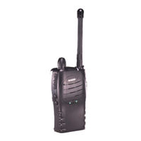
Maxon SP210 Service Manual (95 pages)
Maxon Telecom Two-Way Radio Service Manual
Brand:
Maxon
| Category:
Two-Way Radio
| Size: 3 MB
Table of Contents
Table of Contents
5
WARNINGS Issue
8
Amendments to this Manual
9
Using this Manual
9
Introduction
9
7 Programming
9
Spare Parts
9
Contact Information
10
2 Specifications
11
General
11
3 Accessories & Options
13
Pre-Install Check
13
Accessories and Options
13
4 Installation, Commissioning & Alignment
15
Connections
15
Figure 4-1 - Connections and Controls
15
Commissioning
16
Figure 4-2 - Connections
16
Figure 4-3 - Hirose Connector
16
Figure 4-4 - Commissioning Test Setup Using SK2055 Service Kit
16
Figure 4-5 - Commissioning Kit
17
Figure 4-6 - Test Equipment Set-Up Using Discrete Test Equipment
18
Figure 4-7 - Test Equipment Set-Up Using a Communications Test Set
18
Figure 4-8 - SK 3100 Service Kit
19
Receiver Performance Tests
20
Transmitter Performance Tests
20
Test Equipment Connection
20
Power Adjustment
21
Figure 4-9 - Back Panel Adjusters
21
Preparation
22
Alignment
22
Disassembly and Re-Assembly of the Radio
23
Figure 4-11 - Replacing the Battery
23
Figure 4-10 - Removal of Battery
23
Figure 4-12 - Replacing the Battery
23
Figure 4-13 - Removing the Belt Clip
23
PLL Alignment
24
Figure 4-14 - Adjustment Points
24
Transmitter Alignment
25
Squelch Sensitivity
25
Figure 4-15 - ACC-2003 Alignment Box Test Setup
26
Receiver Alignment
28
1 Introduction
29
Audio Signal Path
30
Audio ASIC
30
Miscellaneous Signals and Controller
31
Sat Signal Path
31
Figure 5-1 - ASIC Block Diagram
31
Audio/Sat Circuits
32
Common RF Circuits
33
Figure 5-2 - Synthesiser Block Diagram
33
Transmitter
35
Figure 5-3 - Transmitter Block Diagram
35
Receiver
36
Figure 5-4 - Receiver Block Diagram
36
Diagnostic Function
39
5 Detailed Functional Description
29
Common Circuits
29
6 Troubleshooting
39
Table 6-1 - Diagnostics
39
Table 6-2 - Troubleshooting Chart
40
Transistors (Main Circuit)
41
Voltage Charts
41
Table 6-3 - Main Circuit Transistor Voltages
41
Integrated Circuits
42
Table 6-4 - Integrated Circuit Voltages (Receive)
42
Table 6-5 - Integrated Circuit Voltages (Transmit)
42
Figure 6-1 – Legend Layout for Top Side of Digital PCB
43
Getting Started
47
8 Exploded Mechanical Drawings & Parts Lists
51
Parts List
51
Spare Parts
51
Vco
52
Mechanical Parts
53
Table 8-1 - Parts List for Exploded Mechanical Drawing 1
54
Figure 8-3 – Exploded Mechanical Drawing 3
56
Table 8-2 - Parts List for Exploded Mechanical Drawing 2
56
SL100 VHF Parts List
58
V2 Control Circuit
58
V2 Rf
60
TCXO Assembly
63
V2 Vco
64
V2 Front End
64
SL100 UHF Parts List
65
U2 Control Circuit
65
U2 Rf
67
Tcxo
70
9 Circuit Diagrams & Pcb Layouts
73
Figure 9-1 – Digital Board Layout Top Side
75
Figure 9-5 – Front-End Board Layout
79
Figure 9-6 – VCO Board Layout
79
Figure 9-7 – TCXO Board Layout
80
10 Spare Parts
81
Component Replacement
82
Operation
85
11 Appendix - Acc-2003 Alignment Box
85
Calibration Program
85
Appendix A - Acc-2003 Interface Box
85
Adjustment of ASIC Values
88
Transmit Adjustments
90
Receive Adjustments
91
Default Settings
92
V1 Band Default Settings
92
Table 3 - V1 Default Frequency Table
92
Table 4 - V1 Default ASIC Settings
92
V2 Band Default Settings
93
Table 5 - V2 Default Frequency Table
93
Table 6 - V2 Default ASIC Settings
93
U1 Band Default Settings
94
Table 7 - U1 Default Frequency Table
94
Table 8 - U1 Default ASIC Settings
94
U2 Band Default Settings
95
Table 9 - U2 Default Frequency Table
95
Table 10 - U2 Default ASIC Settings
95
Advertisement
Maxon SP210 Manual (10 pages)
Brand:
Maxon
| Category:
Radio
| Size: 0 MB
Table of Contents
Table of Contents
2
Safety Information
3
Unpacking Information
3
SP-210 Features
3
Description of Radio Components
4
Antenna Installation
5
Installing and Removing the Battery Pack
5
Attaching and Removing the Belt Clip
5
Battery Charging and Care
5
Power On-Volume
6
Channel Select
6
Transmit
6
Power off
6
Status Indicators and Audible Alert Tones
7
Scan Modes
7
Normal Channel Scan
7
Priority Channel Scan
7
Other Scanning Features
8
Look Back
8
Scan Channel Delete
8
CTCSS/DCS Scanning
8
Normal Scan TX
8
Priority Scan TX
8
Priority Only TX
8
Receive Only Scan
8
Scan List Edit
8
Licensing and Service Information
9
Recycling/Disposal of Batteries
9
Software Copyrights
9
Maintenance
10
Advertisement
Related Products
Maxon SP-200 Series
Maxon SP-300 Series
Maxon SP-200K Series
Maxon SP-100G
Maxon SP-100
Maxon SP-100H
Maxon SP-100U
Maxon SP-1402
Maxon SP-1102
Maxon S5
Maxon Categories
Radio
Lifting Systems
Two-Way Radio
Music Pedal
Automobile Accessories
More Maxon Manuals
Login
Sign In
OR
Sign in with Facebook
Sign in with Google
Upload manual
Upload from disk
Upload from URL